How to Use PowerBoost 500 Basic Terminal: Examples, Pinouts, and Specs
Introduction
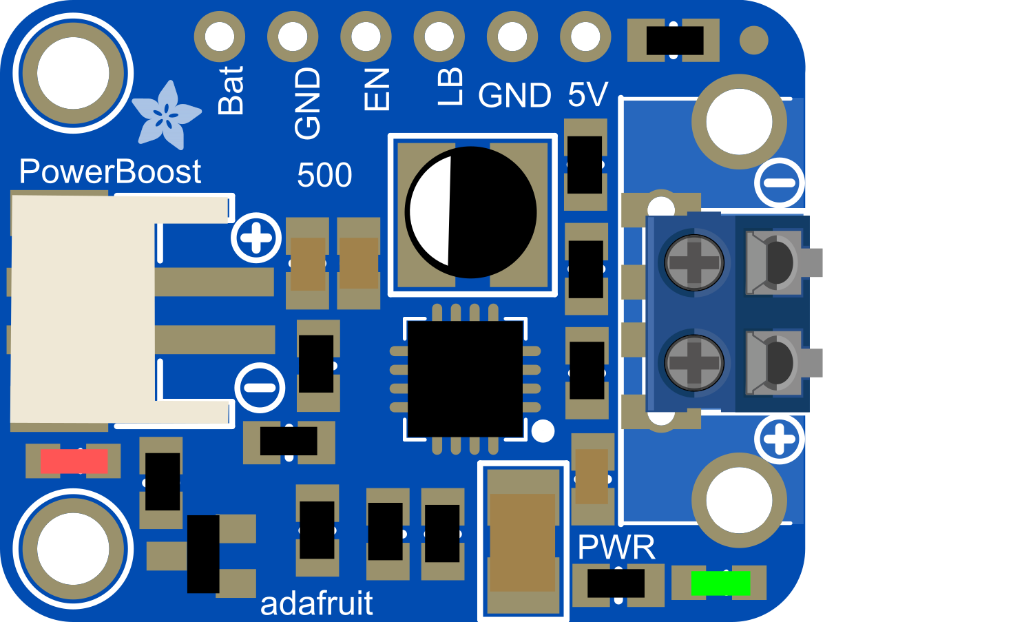
The PowerBoost 500 Basic Terminal is a versatile and compact power supply module designed to provide a stable 5V output from a single lithium polymer (LiPo) battery. It is an essential component for hobbyists and professionals who need a reliable power source for their projects. The PowerBoost 500 Basic is particularly useful for portable electronics, wearables, and small embedded systems where space is at a premium and battery life is critical.
Explore Projects Built with PowerBoost 500 Basic Terminal

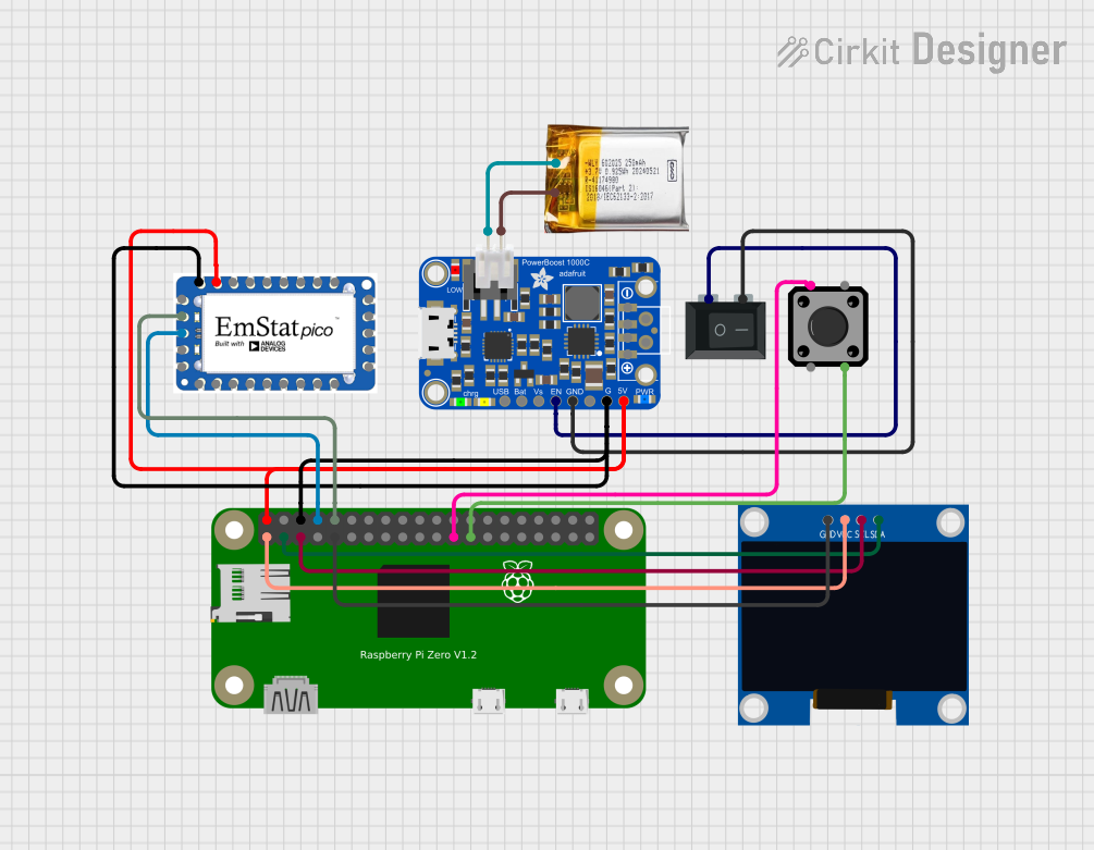

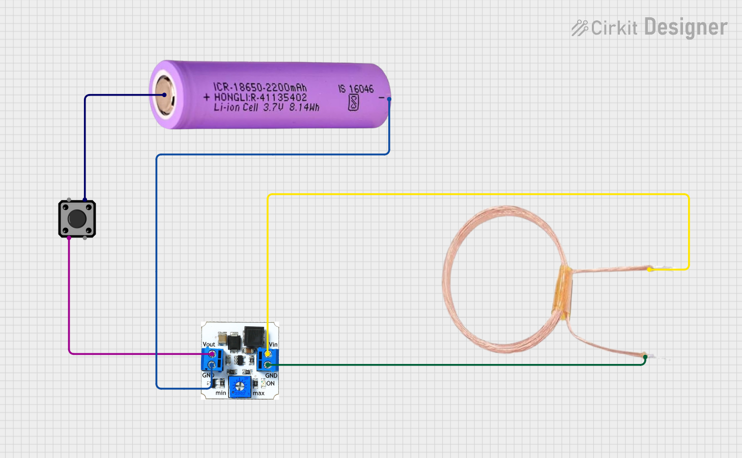
Explore Projects Built with PowerBoost 500 Basic Terminal
Common Applications and Use Cases
- Portable USB chargers
- Wearable electronics
- Battery-powered Raspberry Pi or Arduino projects
- Small robotics
- IoT devices
Technical Specifications
Key Technical Details
- Input Voltage: 3.7V nominal (from LiPo battery)
- Output Voltage: 5V regulated output
- Maximum Output Current: 500mA
- Quiescent Current: <5mA
- Efficiency: 85-95% typical (varies with load)
- Battery Charging: No onboard charging circuitry
Pin Configuration and Descriptions
| Pin Name | Description |
|---|---|
| BAT | Battery input terminal for LiPo battery (+) |
| GND | Ground terminal |
| 5V | Regulated 5V output terminal |
| EN | Enable pin (active high) |
| GND | Ground terminal for Enable pin |
Usage Instructions
How to Use the Component in a Circuit
Connecting the Battery:
- Connect the positive terminal of the LiPo battery to the
BATterminal. - Connect the negative terminal of the battery to the
GNDterminal adjacent toBAT.
- Connect the positive terminal of the LiPo battery to the
Enabling the PowerBoost:
- To enable the PowerBoost 500 Basic, connect the
ENpin toGND. This can be done with a switch or jumper. - If you want to control the enable function programmatically, connect the
ENpin to a GPIO pin on your microcontroller.
- To enable the PowerBoost 500 Basic, connect the
Drawing Power:
- Connect your device's power input to the
5VandGNDterminals on the PowerBoost 500 Basic. - Ensure that your device does not draw more than 500mA to prevent overloading the PowerBoost.
- Connect your device's power input to the
Important Considerations and Best Practices
- Do not exceed the recommended input voltage as it may damage the PowerBoost 500 Basic.
- Ensure that the polarity of the battery connections is correct to prevent damage.
- Avoid placing the PowerBoost 500 Basic in environments with extreme temperatures or humidity.
- When not in use, disconnect the battery to prevent draining.
Troubleshooting and FAQs
Common Issues
No Output Voltage:
- Check battery connections and charge.
- Ensure the
ENpin is connected toGND.
Output Voltage Drops Under Load:
- The device connected may be drawing more than 500mA. Check the current draw of your device.
PowerBoost Heats Up:
- This can happen under maximum load. Ensure adequate ventilation and avoid enclosing the PowerBoost without airflow.
Solutions and Tips for Troubleshooting
- Double-check all connections, especially the polarity of the battery.
- Measure the battery voltage to ensure it is within the operating range.
- Use a multimeter to verify the output voltage is a stable 5V.
- If using the
ENpin, ensure it is properly controlled by your microcontroller or switch.
FAQs
Q: Can I recharge the LiPo battery using the PowerBoost 500 Basic? A: No, the PowerBoost 500 Basic does not include charging circuitry. You will need a separate LiPo charger.
Q: What happens if I connect a load that draws more than 500mA? A: The PowerBoost 500 Basic may overheat, shut down, or get damaged. Always ensure your load is within the specified limits.
Q: Can I use the PowerBoost 500 Basic with devices other than USB-powered ones? A: Yes, as long as the device operates at 5V and requires 500mA or less.
Q: Is the output voltage adjustable? A: No, the PowerBoost 500 Basic provides a fixed 5V output.
Q: How do I know if the PowerBoost 500 Basic is on? A: You can measure the output voltage with a multimeter or connect an LED (with a current-limiting resistor) to the output to serve as a power indicator.
For any further assistance or technical support, please contact the manufacturer or visit the community forums dedicated to electronics enthusiasts.