How to Use Motoron M1U256: Examples, Pinouts, and Specs

Introduction
The Motoron M1U256 is a compact and versatile motor controller designed to drive DC motors with precision. It features an integrated microcontroller that enables seamless control of motor speed and direction through I2C communication. With the ability to control up to 256 motors, the M1U256 is an excellent choice for robotics, automation, and other applications requiring scalable motor control.
Explore Projects Built with Motoron M1U256
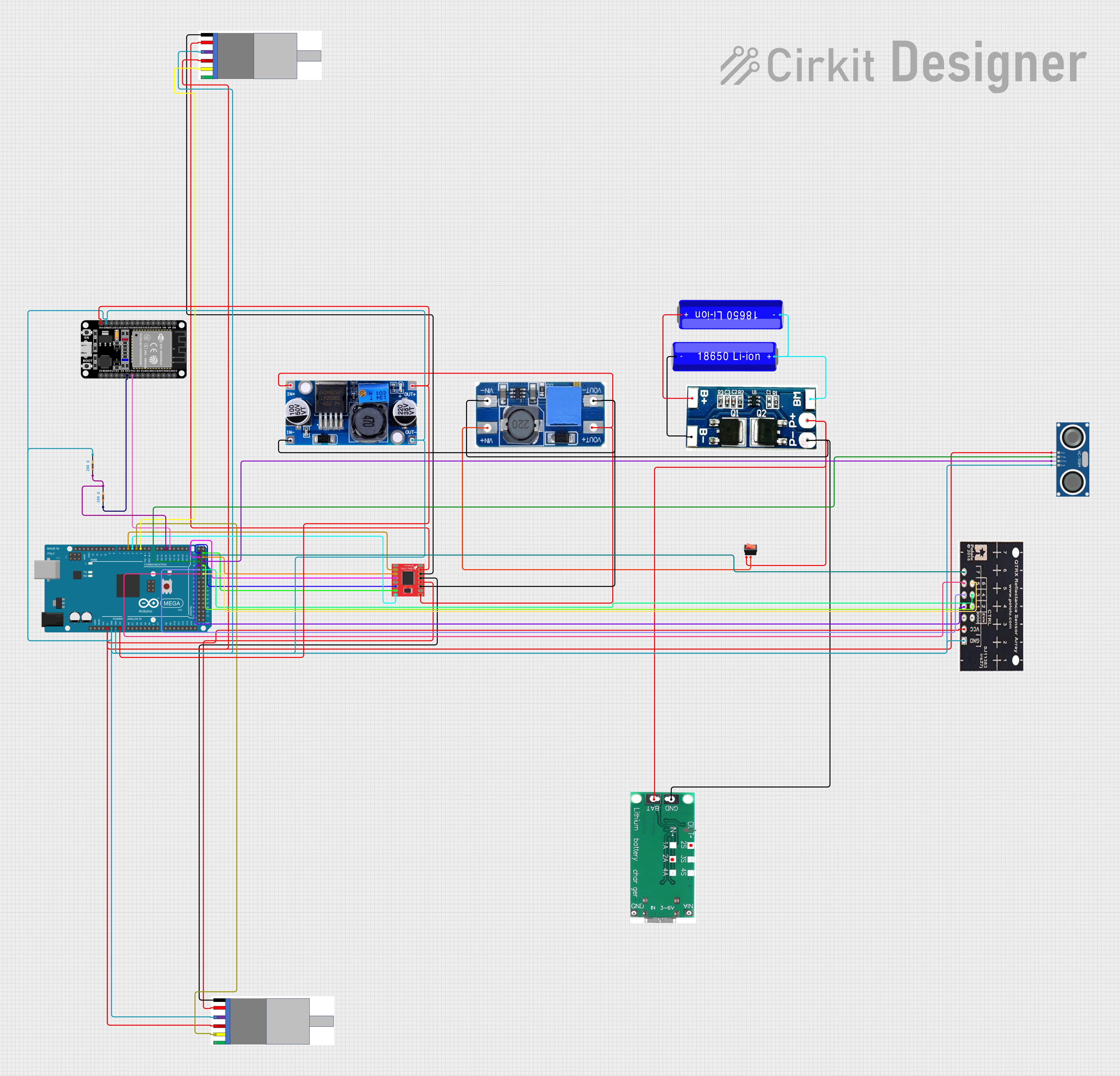
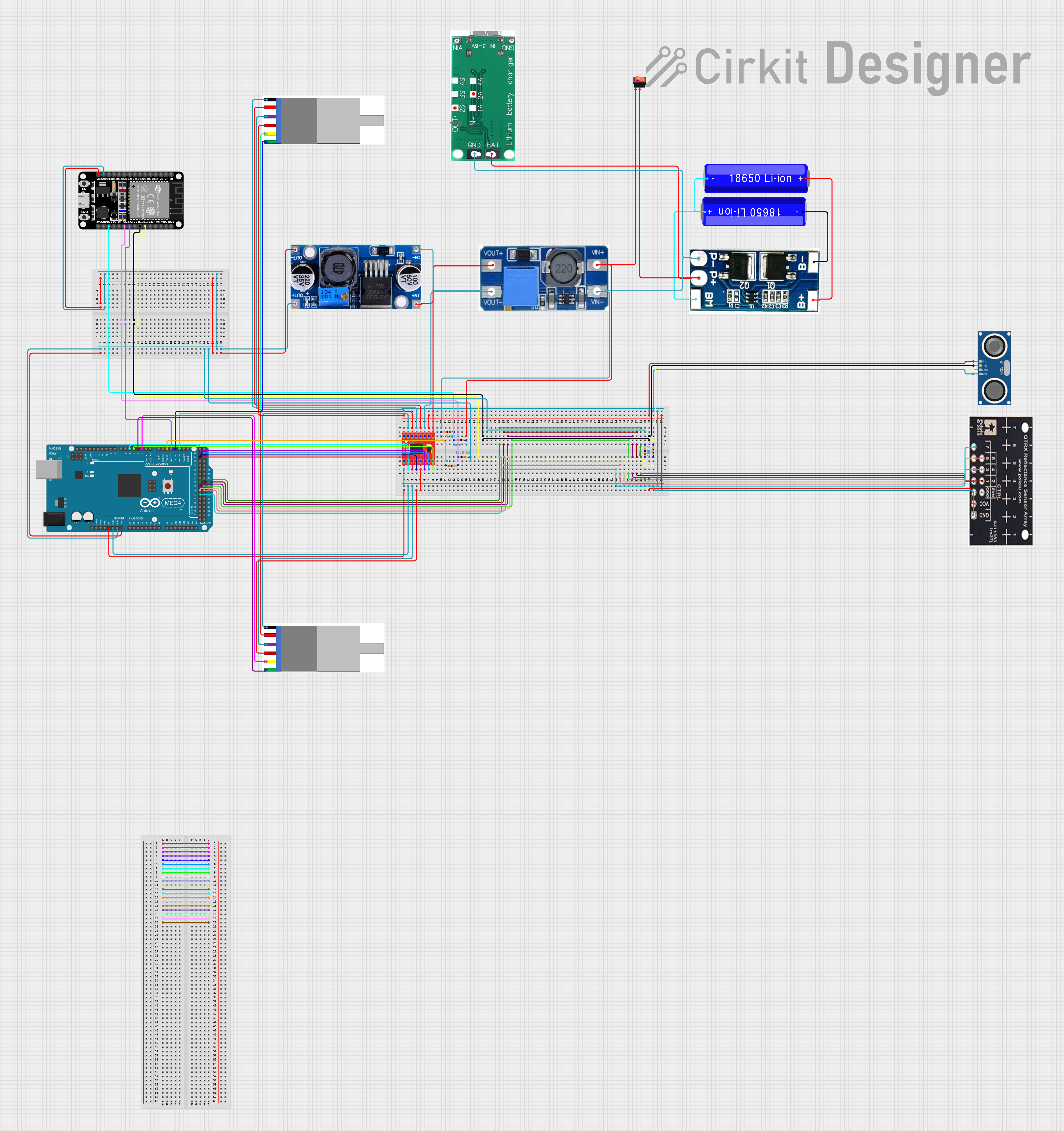
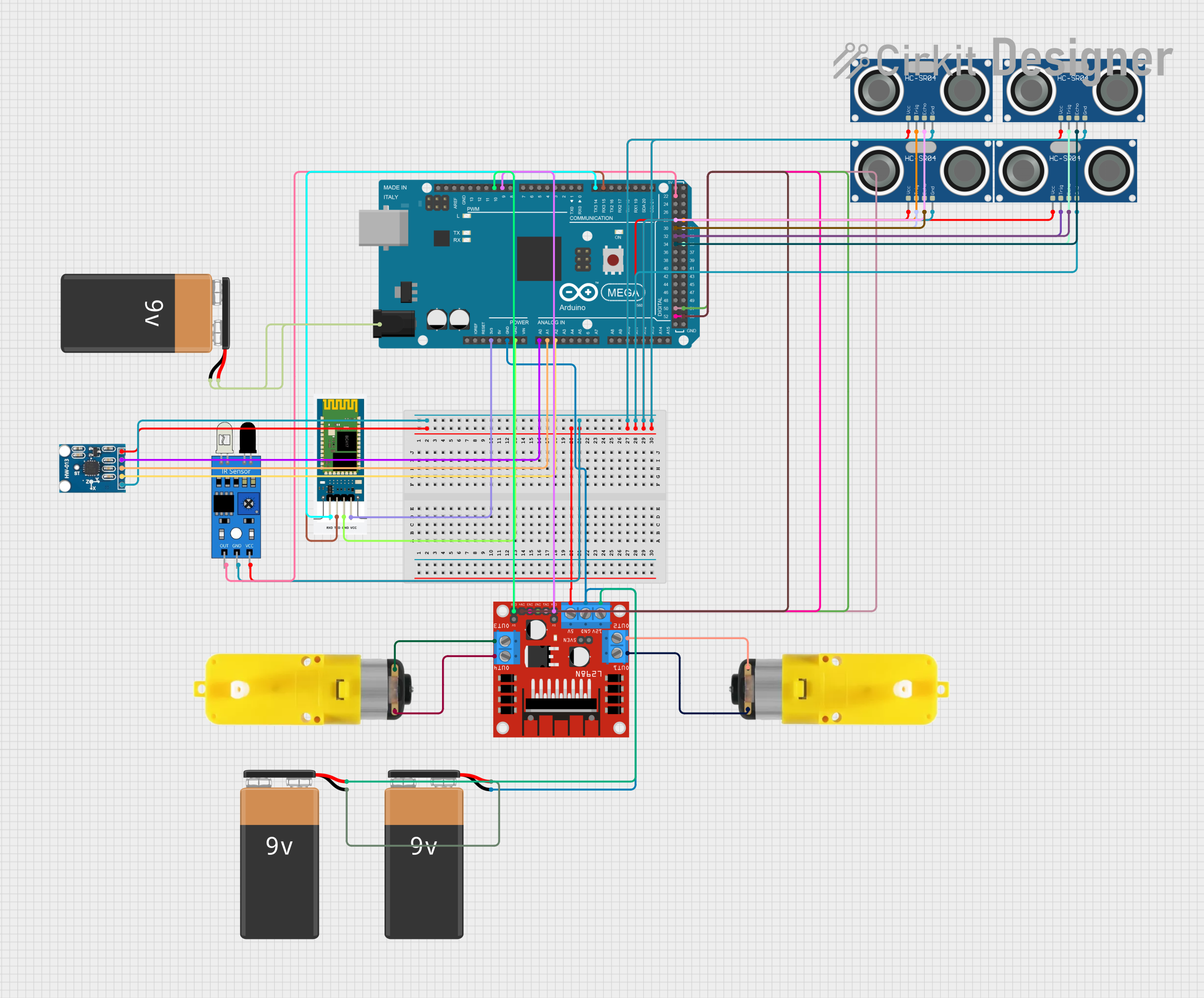
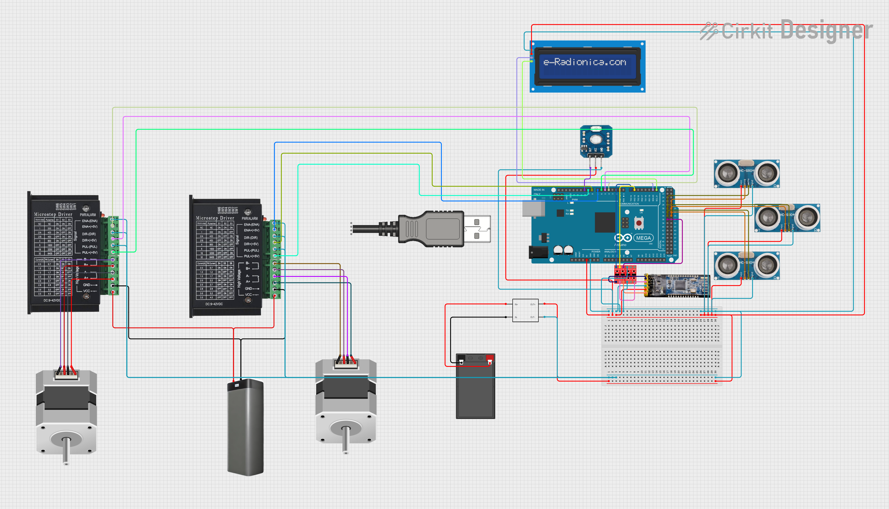
Explore Projects Built with Motoron M1U256
Common Applications and Use Cases
- Robotics: Controlling multiple motors for robotic arms, wheels, or actuators.
- Industrial Automation: Driving conveyor belts, pumps, or other machinery.
- DIY Projects: Building motorized systems for hobbyist applications.
- Educational Tools: Teaching motor control and I2C communication in electronics courses.
Technical Specifications
The following table outlines the key technical details of the Motoron M1U256:
| Parameter | Value |
|---|---|
| Operating Voltage | 4.5V to 48V |
| Maximum Motor Current | 1.7A per motor channel |
| Communication Interface | I2C |
| Number of Motors Supported | Up to 256 (via I2C chaining) |
| PWM Frequency Range | 1 kHz to 20 kHz |
| Dimensions | 1.0" × 1.2" (25.4 mm × 30.5 mm) |
| Operating Temperature | -40°C to 85°C |
Pin Configuration and Descriptions
The M1U256 has a simple pinout for easy integration into your circuit. Below is the pin configuration:
| Pin Name | Type | Description |
|---|---|---|
| VIN | Power Input | Main power supply for the motors (4.5V to 48V). |
| GND | Ground | Common ground for the power supply and logic. |
| SDA | I2C Data Line | Serial data line for I2C communication. |
| SCL | I2C Clock Line | Serial clock line for I2C communication. |
| RESET | Input | Active-low reset pin to restart the controller. |
| M1+, M1- | Motor Output | Terminals for connecting the first motor. |
| M2+, M2- | Motor Output | Terminals for connecting the second motor. |
Usage Instructions
How to Use the M1U256 in a Circuit
- Power Supply: Connect the VIN pin to a power source (4.5V to 48V) and the GND pin to the ground of your circuit.
- Motor Connections: Attach the DC motor leads to the M1+/M1- or M2+/M2- terminals.
- I2C Communication: Connect the SDA and SCL pins to the corresponding I2C pins on your microcontroller (e.g., Arduino UNO).
- Address Configuration: The M1U256 supports multiple devices on the same I2C bus. Configure the I2C address using the appropriate commands or settings in your microcontroller code.
- Reset (Optional): Use the RESET pin to restart the controller if needed.
Important Considerations and Best Practices
- Current Limitations: Ensure the motor current does not exceed 1.7A per channel to avoid damage.
- Power Supply: Use a stable power source within the specified voltage range to ensure reliable operation.
- I2C Pull-Up Resistors: If your circuit does not already include pull-up resistors on the SDA and SCL lines, add 4.7kΩ resistors to ensure proper I2C communication.
- Heat Dissipation: For high-current applications, consider adding a heatsink or ensuring adequate ventilation.
Example Code for Arduino UNO
Below is an example of how to control a motor connected to the M1U256 using an Arduino UNO:
#include <Wire.h> // Include the Wire library for I2C communication

#define MOTORON_I2C_ADDRESS 0x10 // Replace with the actual I2C address of your M1U256

void setup() {
  Wire.begin(); // Initialize I2C communication
  Serial.begin(9600); // Initialize serial communication for debugging

  // Set motor speed and direction
  setMotorSpeed(1, 100); // Motor 1, speed 100 (range: -255 to 255)
}

void loop() {
  // Example: Change motor speed every 2 seconds
  for (int speed = -255; speed <= 255; speed += 50) {
    setMotorSpeed(1, speed); // Update motor speed
    delay(2000); // Wait for 2 seconds
  }
}

// Function to set motor speed and direction
void setMotorSpeed(uint8_t motor, int16_t speed) {
  Wire.beginTransmission(MOTORON_I2C_ADDRESS); // Start I2C communication
  Wire.write(0x01); // Command to set motor speed
  Wire.write(motor); // Motor number (1-256)
  Wire.write((uint8_t)(speed & 0xFF)); // Low byte of speed
  Wire.write((uint8_t)((speed >> 8) & 0xFF)); // High byte of speed
  Wire.endTransmission(); // End I2C communication
}
Troubleshooting and FAQs
Common Issues and Solutions
Motor Not Running
- Cause: Incorrect wiring or insufficient power supply.
- Solution: Double-check all connections and ensure the power supply meets the voltage and current requirements.
I2C Communication Failure
- Cause: Missing or incorrect pull-up resistors on SDA and SCL lines.
- Solution: Add 4.7kΩ pull-up resistors to the SDA and SCL lines if not already present.
Overheating
- Cause: Exceeding the current limit or poor ventilation.
- Solution: Ensure the motor current is within the 1.7A limit and improve airflow around the controller.
Controller Not Responding
- Cause: Incorrect I2C address or firmware issue.
- Solution: Verify the I2C address and reset the controller using the RESET pin.
FAQs
Q: Can the M1U256 control stepper motors?
A: No, the M1U256 is designed for DC motors only.Q: How do I chain multiple M1U256 controllers?
A: Assign unique I2C addresses to each controller and connect them to the same SDA and SCL lines.Q: What happens if I exceed the current limit?
A: The controller may overheat or shut down to protect itself. Always stay within the specified current limits.Q: Can I use the M1U256 with a Raspberry Pi?
A: Yes, the M1U256 is compatible with any device that supports I2C communication, including Raspberry Pi.
This concludes the documentation for the Motoron M1U256. For further assistance, refer to the manufacturer's datasheet or support resources.