How to Use DC-DC USB Step Up & Step Down Adjustable Converter Module: Examples, Pinouts, and Specs
Introduction
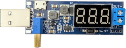
The DC-DC USB Step Up & Step Down Adjustable Converter Module is a versatile power converter designed to regulate voltage levels efficiently. It can both increase (step up) and decrease (step down) input voltage to provide a stable output, making it ideal for powering USB devices from a wide range of voltage sources. This module is particularly useful in applications where the input voltage may vary, such as battery-powered systems or solar panels.
Explore Projects Built with DC-DC USB Step Up & Step Down Adjustable Converter Module


Explore Projects Built with DC-DC USB Step Up & Step Down Adjustable Converter Module
Common Applications and Use Cases
- Powering USB devices from non-standard voltage sources (e.g., 3.7V lithium batteries).
- Regulating voltage in portable electronics and DIY projects.
- Providing stable power for Arduino, Raspberry Pi, or other microcontroller-based systems.
- Charging USB devices from unconventional power sources like solar panels.
Technical Specifications
Key Technical Details
- Input Voltage Range: 3V to 15V DC
- Output Voltage Range: 5V (fixed USB output) or adjustable (via potentiometer)
- Output Current: Up to 2A (depending on input voltage and load)
- Efficiency: Up to 92% (varies with input/output conditions)
- USB Output Port: Standard Type-A USB
- Dimensions: Approximately 50mm x 25mm x 12mm
- Protection Features: Overcurrent, overvoltage, and short-circuit protection
Pin Configuration and Descriptions
The module typically has the following input and output connections:
| Pin/Port Name | Type | Description |
|---|---|---|
VIN+ |
Input | Positive input voltage terminal (3V to 15V DC). |
VIN- |
Input | Negative input voltage terminal (ground). |
USB Output |
Output | Standard USB Type-A port for 5V output (fixed or adjustable via potentiometer). |
Potentiometer |
Adjustment | Used to adjust the output voltage (if adjustable output is supported). |
Usage Instructions
How to Use the Component in a Circuit
Connect the Input Voltage:
- Attach the positive voltage source to the
VIN+terminal and the ground to theVIN-terminal. - Ensure the input voltage is within the specified range (3V to 15V DC).
- Attach the positive voltage source to the
Adjust the Output Voltage (if applicable):
- Use the onboard potentiometer to set the desired output voltage.
- If using the USB port, the output is typically fixed at 5V unless the module supports adjustable USB output.
Connect the Load:
- Plug the USB device or circuit into the USB Type-A port for power.
- Ensure the load does not exceed the maximum output current (2A).
Power On:
- Turn on the input power source. The module will regulate the voltage and provide a stable output.
Important Considerations and Best Practices
- Heat Dissipation: At high currents, the module may generate heat. Ensure proper ventilation or add a heatsink if necessary.
- Input Voltage: Always verify that the input voltage is within the specified range to avoid damaging the module.
- Load Current: Do not exceed the maximum output current (2A) to prevent overheating or triggering the protection features.
- Polarity: Double-check the polarity of the input connections to avoid damage.
Example: Using with an Arduino UNO
To power an Arduino UNO using this module:
- Connect a 3.7V lithium battery to the
VIN+andVIN-terminals. - Adjust the potentiometer to set the output voltage to 5V (if adjustable).
- Plug the Arduino UNO into the USB output port of the module.
Here is an example Arduino sketch to test the setup:
// Example Arduino code to blink an LED
// This code assumes the Arduino UNO is powered via the USB output of the module.

void setup() {
  pinMode(13, OUTPUT); // Set pin 13 as an output for the onboard LED
}

void loop() {
  digitalWrite(13, HIGH); // Turn the LED on
  delay(1000);            // Wait for 1 second
  digitalWrite(13, LOW);  // Turn the LED off
  delay(1000);            // Wait for 1 second
}
Troubleshooting and FAQs
Common Issues and Solutions
No Output Voltage:
- Cause: Incorrect input connections or insufficient input voltage.
- Solution: Verify the polarity and ensure the input voltage is within the 3V to 15V range.
Overheating:
- Cause: Excessive load current or poor ventilation.
- Solution: Reduce the load current or improve ventilation. Consider adding a heatsink.
Output Voltage Fluctuations:
- Cause: Unstable input voltage or incorrect potentiometer adjustment.
- Solution: Ensure the input voltage is stable and adjust the potentiometer carefully.
USB Device Not Charging:
- Cause: Insufficient output current or incorrect voltage setting.
- Solution: Verify the load current requirements and ensure the output voltage is set to 5V.
FAQs
Can this module charge a smartphone?
- Yes, as long as the input voltage and current are sufficient to meet the smartphone's charging requirements.
Is the output voltage always 5V?
- The USB output is typically fixed at 5V, but some modules allow adjustment via the potentiometer.
Can I use this module with a solar panel?
- Yes, as long as the solar panel's output voltage is within the 3V to 15V range.
What happens if I reverse the input polarity?
- The module may be damaged. Always double-check the polarity before connecting the input voltage.