
How to Use JUMPER-3: Examples, Pinouts, and Specs
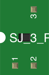
 Design with JUMPER-3 in Cirkit Designer
Introduction
The JUMPER-3 (Manufacturer Part ID: SJ_3_PASTE1_2) is a versatile electronic component designed to provide a simple and reliable way to connect two points in a circuit. Manufactured by Generic, this jumper is commonly used to bypass switches, configure settings on circuit boards, or enable/disable specific features in electronic devices. Its compact design and ease of use make it an essential component for prototyping, testing, and permanent installations.
Explore Projects Built with JUMPER-3
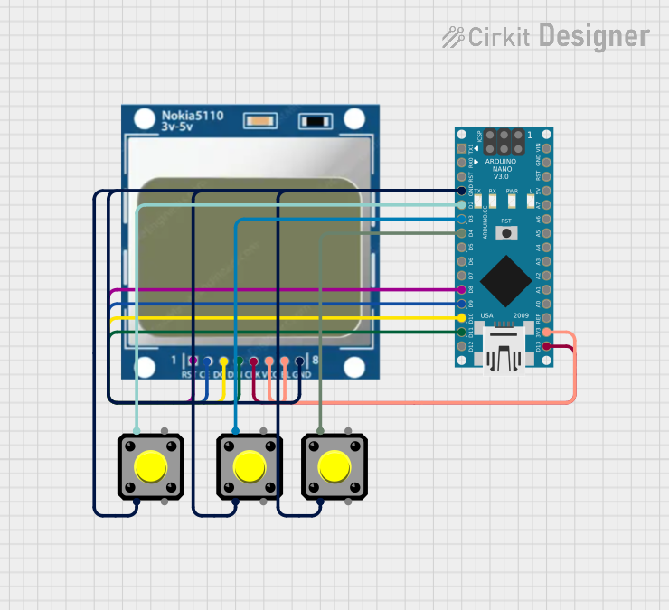 Open Project in Cirkit Designer
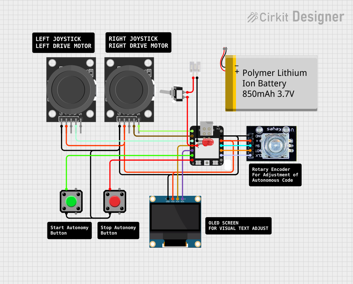 Open Project in Cirkit Designer
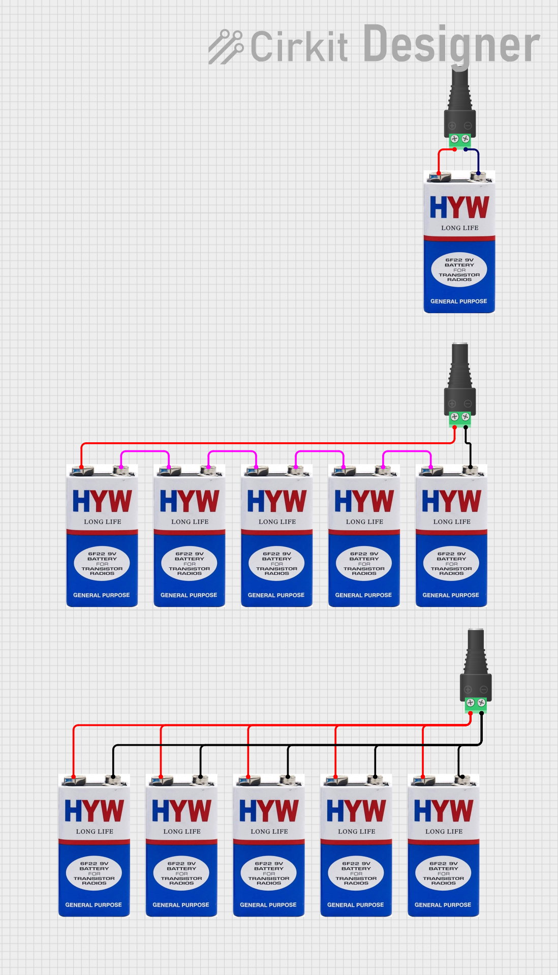 Open Project in Cirkit Designer
 Open Project in Cirkit Designer
Explore Projects Built with JUMPER-3
Open Project in Cirkit DesignerOpen Project in Cirkit DesignerOpen Project in Cirkit DesignerOpen Project in Cirkit DesignerCommon Applications
- Configuring hardware settings on motherboards or development boards.
- Bypassing switches or enabling specific circuit paths.
- Prototyping and testing electronic circuits.
- Shorting pins for debugging purposes.
Technical Specifications
The JUMPER-3 is a passive component with no active electrical properties. Below are its key specifications:
| Parameter | Value |
|---|---|
| Manufacturer | Generic |
| Part ID | SJ_3_PASTE1_2 |
| Material | Conductive metal with plastic insulation |
| Pin Spacing | 2.54 mm (standard pitch) |
| Maximum Current Rating | 3 A |
| Maximum Voltage Rating | 50 V |
| Operating Temperature | -40°C to 85°C |
| Dimensions | 5 mm x 2.5 mm x 2 mm |
Pin Configuration and Description
The JUMPER-3 does not have a traditional pinout but is designed to connect two adjacent pins on a standard 2.54 mm pitch header. Below is a description of its functionality:
| Pin | Description |
|---|---|
| Pin 1 | Connects to the first header pin. |
| Pin 2 | Connects to the second header pin. |
Usage Instructions
How to Use the JUMPER-3 in a Circuit
- Identify the Header Pins: Locate the two adjacent pins on the circuit board that need to be connected.
- Position the Jumper: Align the JUMPER-3 with the two pins and gently press it down until it fits snugly.
- Verify the Connection: Ensure the jumper is securely seated and that the connection is stable.
Important Considerations
- Pin Spacing: Ensure the header pins have a 2.54 mm pitch, as the JUMPER-3 is designed for this standard spacing.
- Current and Voltage Limits: Do not exceed the maximum current rating of 3 A or the voltage rating of 50 V to avoid damage.
- Temperature Range: Operate the jumper within the specified temperature range (-40°C to 85°C) to maintain reliability.
- Avoid Excessive Force: Do not apply excessive force when inserting or removing the jumper to prevent damage to the pins or the jumper itself.
Example: Using JUMPER-3 with an Arduino UNO
The JUMPER-3 can be used to configure settings or enable features on an Arduino UNO. For example, it can be used to connect the RESET-EN header to enable or disable the auto-reset functionality.
// Example: Using JUMPER-3 to enable/disable auto-reset on Arduino UNO
// Place the JUMPER-3 on the RESET-EN header to enable auto-reset.
// Remove the JUMPER-3 to disable auto-reset functionality.

// Note: No additional code is required for this hardware configuration.
// The jumper simply connects or disconnects the RESET-EN pins.
Troubleshooting and FAQs
Common Issues
Loose Connection:
- Problem: The jumper does not stay securely on the pins.
- Solution: Ensure the pins are clean and free of debris. Check if the jumper is damaged or worn out and replace it if necessary.
Incorrect Pin Spacing:
- Problem: The jumper does not fit the header pins.
- Solution: Verify that the header pins have a 2.54 mm pitch. The JUMPER-3 is not compatible with other pin spacings.
Overheating:
- Problem: The jumper becomes hot during operation.
- Solution: Ensure the current and voltage ratings are not exceeded. If the issue persists, inspect the circuit for faults.
FAQs
Q: Can the JUMPER-3 be reused?
A: Yes, the JUMPER-3 is reusable as long as it is not physically damaged or worn out.Q: Is the JUMPER-3 compatible with breadboards?
A: Yes, the JUMPER-3 can be used with breadboards that have a 2.54 mm pin spacing.Q: How do I know if the jumper is making a proper connection?
A: Use a multimeter to check continuity between the two connected pins. A successful connection will show zero or very low resistance.Q: Can I use the JUMPER-3 for high-power applications?
A: No, the JUMPER-3 is designed for low-power applications with a maximum current rating of 3 A and voltage rating of 50 V.
By following this documentation, users can effectively utilize the JUMPER-3 in their electronic projects and troubleshoot any issues that may arise.