
How to Use Self-Lock Push Button Switch: Examples, Pinouts, and Specs
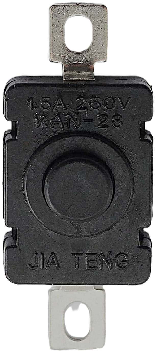
 Design with Self-Lock Push Button Switch in Cirkit Designer
Introduction
The Self-Lock Push Button Switch is a versatile electronic component designed to maintain its position after being pressed. Unlike momentary switches, which return to their default state when released, this switch "locks" into place, allowing for a stable connection in a circuit until it is pressed again to toggle its state. This feature makes it ideal for applications requiring a persistent on/off state without continuous user interaction.
Explore Projects Built with Self-Lock Push Button Switch
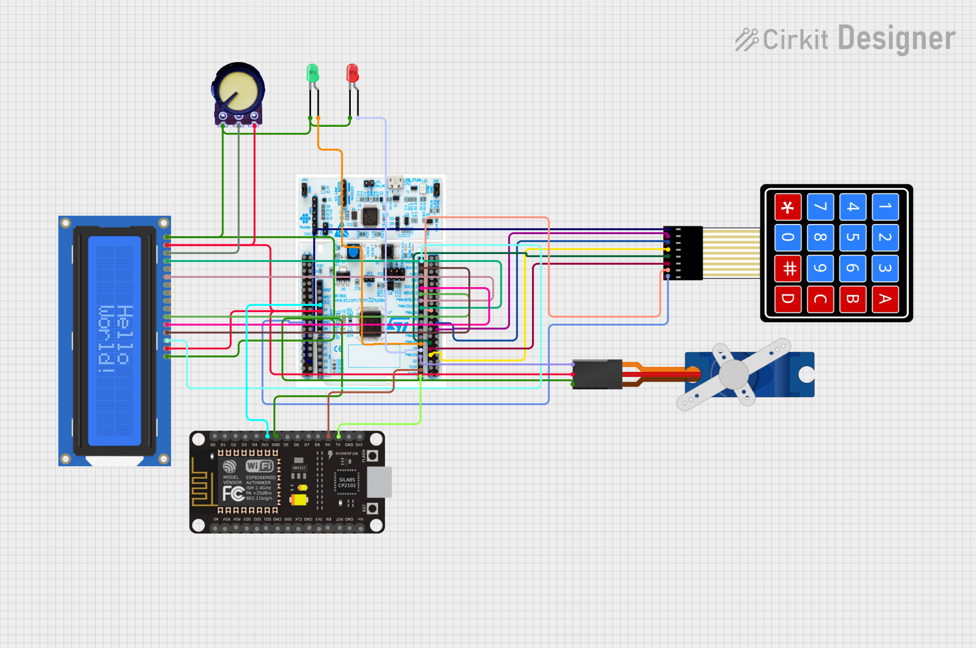 Open Project in Cirkit Designer
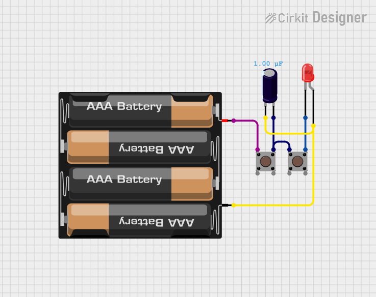 Open Project in Cirkit Designer
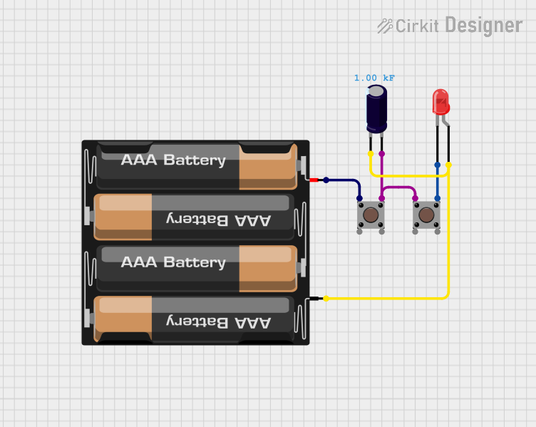 Open Project in Cirkit Designer
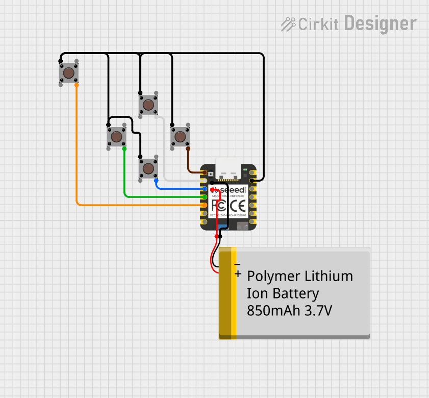 Open Project in Cirkit Designer
Explore Projects Built with Self-Lock Push Button Switch
Open Project in Cirkit DesignerOpen Project in Cirkit DesignerOpen Project in Cirkit DesignerOpen Project in Cirkit DesignerCommon Applications and Use Cases
- Power control for electronic devices
- Mode selection in appliances
- Lighting systems (e.g., toggling LED lights)
- Audio equipment (e.g., muting or enabling sound)
- Industrial control panels
Technical Specifications
Below are the key technical details for the Self-Lock Push Button Switch:
| Parameter | Value |
|---|---|
| Operating Voltage | 3V to 250V (AC/DC, depending on model) |
| Operating Current | 0.5A to 3A (varies by model) |
| Contact Resistance | ≤ 50 mΩ |
| Insulation Resistance | ≥ 100 MΩ |
| Mechanical Durability | ≥ 50,000 cycles |
| Operating Temperature | -20°C to +70°C |
| Mounting Type | Panel mount or PCB mount |
| Switch Type | Latching (self-locking) |
Pin Configuration and Descriptions
The Self-Lock Push Button Switch typically has two or more pins, depending on the model. Below is a general pinout description:
| Pin Number | Label | Description |
|---|---|---|
| 1 | COM | Common terminal for the switch |
| 2 | NO | Normally Open terminal (connected when pressed) |
| 3 (optional) | NC | Normally Closed terminal (disconnected when pressed) |
Note: Some models may only have two pins (COM and NO) for basic on/off functionality.
Usage Instructions
How to Use the Component in a Circuit
- Identify the Pins: Refer to the pin configuration table to identify the COM, NO, and NC pins.
- Connect the Circuit:
- For basic on/off functionality, connect the power source to the COM pin and the load (e.g., an LED) to the NO pin.
- If using the NC pin, the load will remain connected until the button is pressed.
- Mount the Switch: Secure the switch to a panel or PCB as per the mounting type.
- Test the Circuit: Press the button to toggle the connection and verify the functionality.
Important Considerations and Best Practices
- Voltage and Current Ratings: Ensure the switch's ratings match your circuit's requirements to avoid damage.
- Debouncing: Mechanical switches may produce noise or "bouncing" when toggled. Use a capacitor or software debounce logic to stabilize the signal.
- Mounting: If panel mounting, ensure the switch is securely fastened to prevent accidental disconnection.
- Polarity: The switch is non-polarized, so there is no specific orientation for connecting the pins.
Example: Connecting to an Arduino UNO
The Self-Lock Push Button Switch can be used with an Arduino UNO to toggle an LED. Below is an example circuit and code:
Circuit Diagram
- Connect the COM pin of the switch to GND on the Arduino.
- Connect the NO pin of the switch to digital pin 2 on the Arduino.
- Connect an LED to digital pin 13 with a 220Ω resistor in series.
Arduino Code
// Self-Lock Push Button Switch Example
// Toggles an LED on pin 13 when the button is pressed

const int buttonPin = 2;  // Pin connected to the switch's NO terminal
const int ledPin = 13;    // Pin connected to the LED
int buttonState = LOW;    // Variable to store the button state
int ledState = LOW;       // Variable to store the LED state

void setup() {
  pinMode(buttonPin, INPUT_PULLUP); // Set button pin as input with pull-up resistor
  pinMode(ledPin, OUTPUT);         // Set LED pin as output
}

void loop() {
  // Read the button state
  int currentButtonState = digitalRead(buttonPin);

  // Check if the button is pressed (LOW due to pull-up resistor)
  if (currentButtonState == LOW && buttonState == HIGH) {
    // Toggle the LED state
    ledState = !ledState;
    digitalWrite(ledPin, ledState);
    delay(200); // Debounce delay
  }

  // Update the button state
  buttonState = currentButtonState;
}
Note: The
INPUT_PULLUPmode is used to simplify the circuit by eliminating the need for an external pull-up resistor.
Troubleshooting and FAQs
Common Issues and Solutions
Switch Not Responding:
- Cause: Incorrect wiring or loose connections.
- Solution: Double-check the pin connections and ensure the switch is securely mounted.
LED Flickering or Unstable Output:
- Cause: Switch bouncing.
- Solution: Add a debounce circuit (e.g., a capacitor) or implement software debouncing in your code.
Switch Overheating:
- Cause: Exceeding the voltage or current rating.
- Solution: Verify that the circuit's voltage and current are within the switch's specifications.
Switch Stuck in One Position:
- Cause: Mechanical failure or debris inside the switch.
- Solution: Inspect the switch for damage or contamination and replace if necessary.
FAQs
Q1: Can this switch be used for AC circuits?
A1: Yes, as long as the voltage and current ratings are within the specified range.
Q2: How do I clean a dirty or sticky switch?
A2: Use compressed air or contact cleaner to remove debris. Avoid using water or abrasive materials.
Q3: Can I use this switch for high-power applications?
A3: This switch is suitable for low to moderate power applications. For high-power circuits, use a relay in conjunction with the switch.
Q4: Is the switch waterproof?
A4: Most models are not waterproof. If water resistance is required, look for a sealed or IP-rated version.
By following this documentation, you can effectively integrate the Self-Lock Push Button Switch into your projects and troubleshoot common issues with ease.