How to Use 9 Pin Joystick connector: Examples, Pinouts, and Specs
Documentation for Atari 9-Pin Joystick Connector
1. Introduction
The Atari 9-Pin Joystick Connector is a widely recognized interface used to connect joystick devices to microcontrollers, computers, or gaming consoles. Originally popularized by Atari systems, this connector has become a standard for retro gaming and DIY electronics projects. It allows for the transmission of control signals, such as directional inputs and button presses, from the joystick to the connected device.
Common Applications and Use Cases:
- Retro gaming console projects
- DIY arcade controllers
- Robotics and remote control systems
- Input devices for microcontroller-based projects (e.g., Arduino, Raspberry Pi)
- Custom gaming peripherals
The 9-pin joystick connector is simple to use and provides a reliable interface for reading joystick inputs, making it a favorite among hobbyists and retro gaming enthusiasts.
2. Technical Specifications
The Atari 9-pin joystick connector uses a D-subminiature (D-sub) 9-pin male connector. Below are the key technical details and pin configuration.
Key Technical Details:
| Parameter | Value |
|---|---|
| Connector Type | D-sub 9-pin male |
| Voltage Range | 5V DC (typical for microcontrollers) |
| Current Rating | 10 mA per pin (typical) |
| Signal Type | Digital (on/off) |
| Number of Pins | 9 |
| Material | Metal shell with plastic insulator |
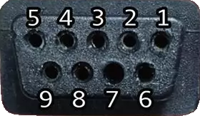
Pin Configuration and Descriptions:
The 9-pin joystick connector has the following pinout:
| Pin Number | Signal Name | Description |
|---|---|---|
| 1 | Up | Joystick up direction signal |
| 2 | Down | Joystick down direction signal |
| 3 | Left | Joystick left direction signal |
| 4 | Right | Joystick right direction signal |
| 5 | Button 1 | Primary action button (e.g., fire button) |
| 6 | +5V | Power supply for the joystick (5V DC) |
| 7 | Ground (GND) | Ground connection |
| 8 | Button 2 | Secondary action button (optional, not always used) |
| 9 | Not Connected | Reserved or unused in most configurations |
3. Usage Instructions
How to Use the 9-Pin Joystick Connector in a Circuit:
Connect the Pins:
- Use a female 9-pin D-sub connector to interface with the joystick.
- Connect the directional pins (1-4) and button pins (5, 8) to the digital input pins of your microcontroller.
- Provide a 5V power supply to Pin 6 and connect Pin 7 to the ground (GND).
Read Inputs:
- Each directional pin and button pin outputs a digital signal (HIGH or LOW).
- When a direction or button is activated, the corresponding pin is pulled LOW (connected to GND).
Debounce Signals:
- Use software or hardware debouncing to ensure stable readings from the joystick.
Optional Pull-Up Resistors:
- If the joystick does not have built-in pull-up resistors, add external pull-up resistors (e.g., 10kΩ) to the directional and button pins.
Best Practices:
- Ensure the joystick is compatible with 5V logic levels before connecting it to a microcontroller.
- Avoid applying excessive force when connecting or disconnecting the joystick to prevent damage to the pins.
- Use a multimeter to verify pin connections if unsure about the joystick's wiring.
4. Example Arduino UNO Integration
Below is an example of how to connect and read inputs from an Atari 9-pin joystick using an Arduino UNO.
Circuit Diagram:
- Pin 1 (Up) → Arduino Digital Pin 2
- Pin 2 (Down) → Arduino Digital Pin 3
- Pin 3 (Left) → Arduino Digital Pin 4
- Pin 4 (Right) → Arduino Digital Pin 5
- Pin 5 (Button 1) → Arduino Digital Pin 6
- Pin 6 (+5V) → Arduino 5V
- Pin 7 (GND) → Arduino GND
Arduino Code:
// Pin definitions for joystick inputs
const int pinUp = 2;      // Joystick Up
const int pinDown = 3;    // Joystick Down
const int pinLeft = 4;    // Joystick Left
const int pinRight = 5;   // Joystick Right
const int pinButton1 = 6; // Joystick Button 1

void setup() {
  // Set joystick pins as inputs with internal pull-up resistors
  pinMode(pinUp, INPUT_PULLUP);
  pinMode(pinDown, INPUT_PULLUP);
  pinMode(pinLeft, INPUT_PULLUP);
  pinMode(pinRight, INPUT_PULLUP);
  pinMode(pinButton1, INPUT_PULLUP);

  // Initialize serial communication for debugging
  Serial.begin(9600);
}

void loop() {
  // Read joystick inputs
  bool up = !digitalRead(pinUp);       // LOW when pressed
  bool down = !digitalRead(pinDown);   // LOW when pressed
  bool left = !digitalRead(pinLeft);   // LOW when pressed
  bool right = !digitalRead(pinRight); // LOW when pressed
  bool button1 = !digitalRead(pinButton1); // LOW when pressed

  // Print joystick state to the Serial Monitor
  Serial.print("Up: "); Serial.print(up);
  Serial.print(" | Down: "); Serial.print(down);
  Serial.print(" | Left: "); Serial.print(left);
  Serial.print(" | Right: "); Serial.print(right);
  Serial.print(" | Button 1: "); Serial.println(button1);

  delay(100); // Small delay for stability
}
5. Troubleshooting and FAQs
Common Issues and Solutions:
Joystick Inputs Not Detected:
- Cause: Incorrect wiring or loose connections.
- Solution: Double-check the pin connections and ensure they match the pinout table.
Erratic or Unstable Readings:
- Cause: Signal noise or lack of debouncing.
- Solution: Add software or hardware debouncing to stabilize the inputs.
Joystick Not Powering On:
- Cause: Missing or incorrect power connection.
- Solution: Verify that Pin 6 is connected to a 5V power source and Pin 7 to GND.
Button or Direction Always Reads as Pressed:
- Cause: Missing pull-up resistors.
- Solution: Enable internal pull-up resistors in the microcontroller or add external pull-up resistors.
FAQs:
Q1: Can I use this connector with a Raspberry Pi?
Yes, but ensure you use appropriate GPIO pins and voltage levels (3.3V logic for Raspberry Pi).
Q2: Can I connect multiple joysticks to one microcontroller?
Yes, but you will need additional GPIO pins for each joystick or use a multiplexer.
Q3: Is this connector compatible with modern gaming systems?
Not directly. It is primarily used for retro gaming or custom projects.
This documentation provides a comprehensive guide to using the Atari 9-pin joystick connector. Whether you're building a retro gaming console or a custom input device, this connector is a versatile and reliable choice.
Explore Projects Built with 9 Pin Joystick connector

Explore Projects Built with 9 Pin Joystick connector