
How to Use ESPC2-12: Examples, Pinouts, and Specs
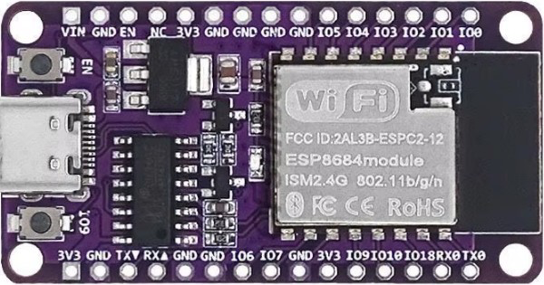
 Design with ESPC2-12 in Cirkit Designer
Introduction
The ESPC2-12 is a compact, low-power microcontroller module featuring built-in Wi-Fi connectivity. It is based on the ESP8266 chip, which is widely recognized for its robust performance in IoT applications. The module supports various wireless communication protocols, making it an excellent choice for smart devices, home automation, and industrial IoT projects. Its small form factor and energy efficiency make it suitable for battery-powered devices and space-constrained designs.
Explore Projects Built with ESPC2-12
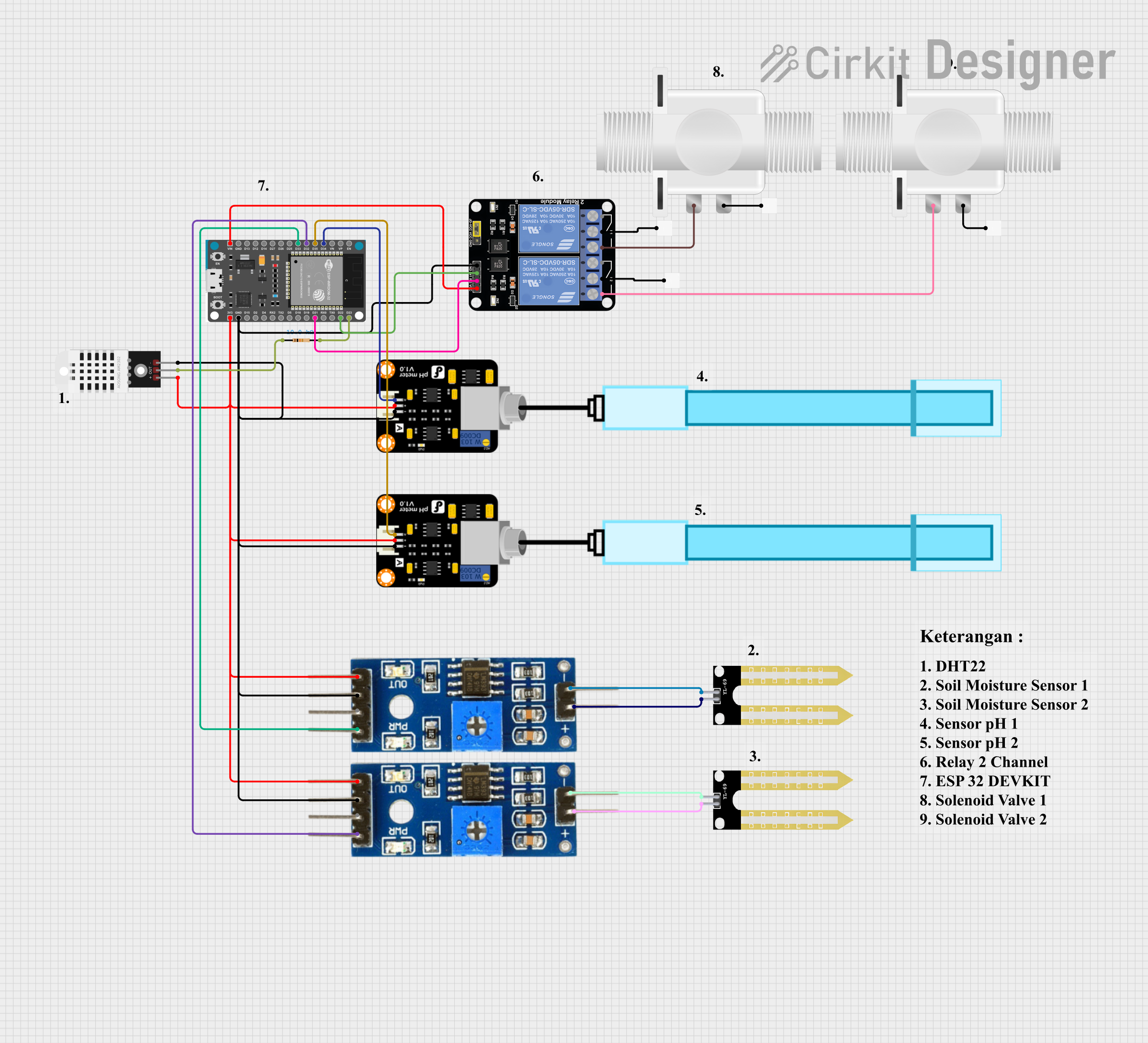 Open Project in Cirkit Designer
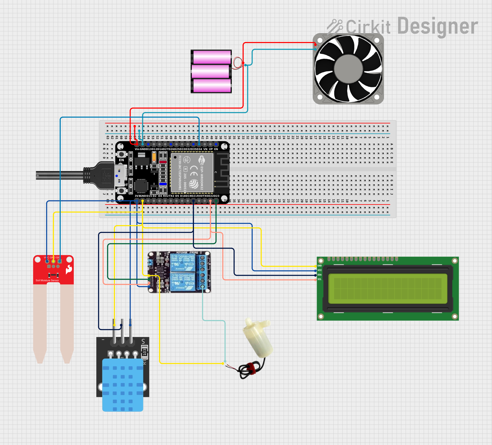 Open Project in Cirkit Designer
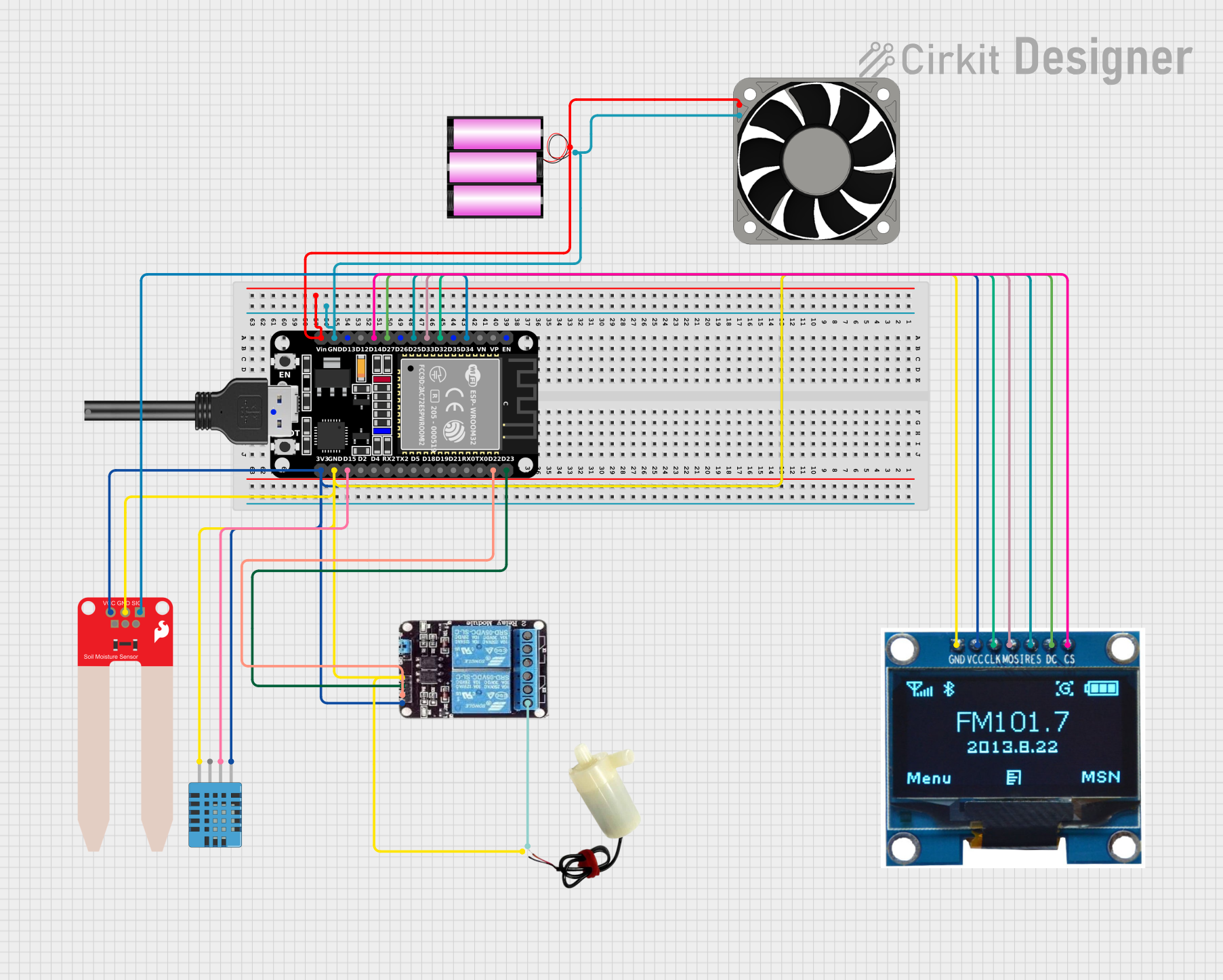 Open Project in Cirkit Designer
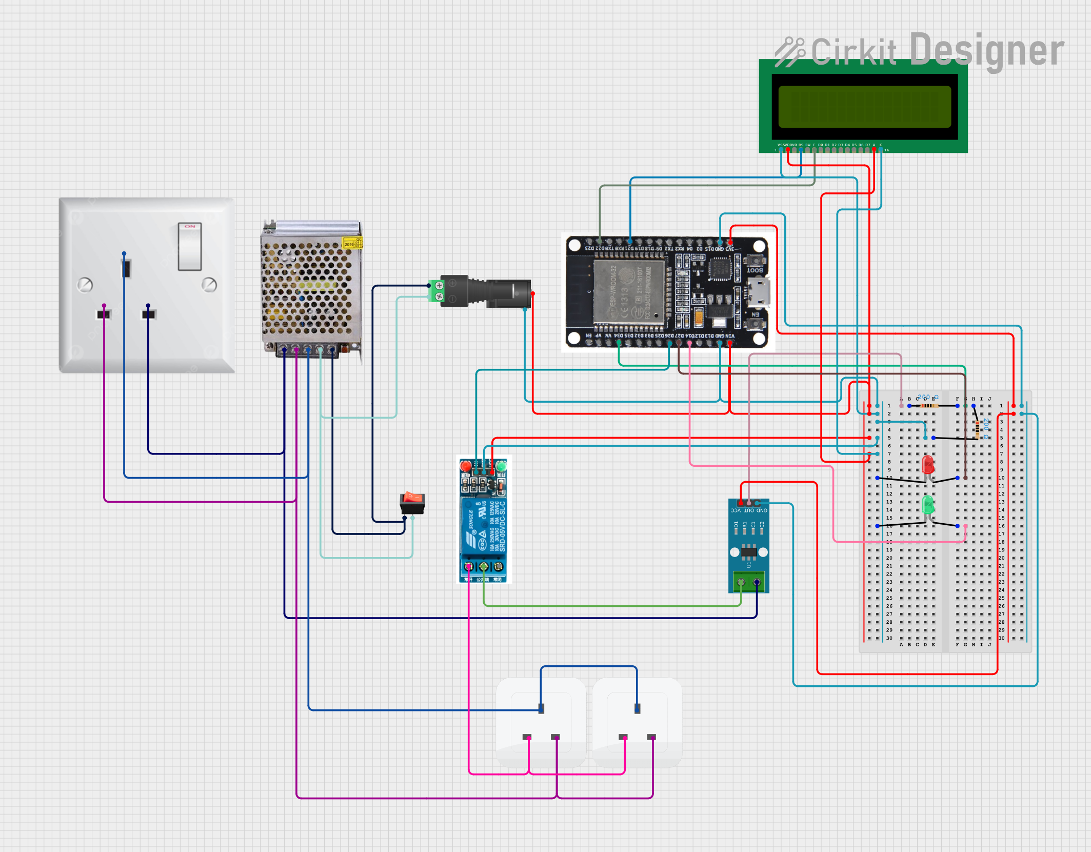 Open Project in Cirkit Designer
Explore Projects Built with ESPC2-12
Open Project in Cirkit DesignerOpen Project in Cirkit DesignerOpen Project in Cirkit DesignerOpen Project in Cirkit DesignerCommon Applications
- Smart home devices (e.g., smart plugs, lights, and thermostats)
- Industrial IoT systems for monitoring and control
- Wearable devices with wireless connectivity
- Remote data logging and sensor networks
- Prototyping and development of IoT projects
Technical Specifications
Key Technical Details
| Parameter | Value |
|---|---|
| Microcontroller | ESP8266 |
| Operating Voltage | 3.0V - 3.6V |
| Flash Memory | 4 MB |
| RAM | 160 KB |
| Wi-Fi Standards | 802.11 b/g/n |
| Frequency Range | 2.4 GHz |
| Power Consumption | 20 mA (idle), 200 mA (peak) |
| GPIO Pins | 11 |
| Communication Protocols | UART, SPI, I2C, PWM |
| Operating Temperature | -40°C to +85°C |
| Dimensions | 24 mm x 16 mm x 3 mm |
Pin Configuration and Descriptions
| Pin Number | Pin Name | Description |
|---|---|---|
| 1 | VCC | Power supply input (3.0V - 3.6V) |
| 2 | GND | Ground connection |
| 3 | TX | UART Transmit pin for serial communication |
| 4 | RX | UART Receive pin for serial communication |
| 5 | GPIO0 | General-purpose I/O pin, can be used for PWM |
| 6 | GPIO1 | General-purpose I/O pin, can be used for SPI |
| 7 | GPIO2 | General-purpose I/O pin, can be used for I2C |
| 8 | GPIO3 | General-purpose I/O pin |
| 9 | EN | Enable pin; active HIGH to power the module |
| 10 | RST | Reset pin; active LOW to reset the module |
| 11 | ADC | Analog-to-digital converter input (10-bit) |
Usage Instructions
How to Use the ESPC2-12 in a Circuit
- Power Supply: Connect the VCC pin to a regulated 3.3V power source and the GND pin to ground. Avoid exceeding the voltage range to prevent damage.
- Enable the Module: Pull the EN pin HIGH to activate the module. Use a pull-up resistor if necessary.
- Serial Communication: Connect the TX and RX pins to a microcontroller or USB-to-serial adapter for programming and debugging.
- GPIO Pins: Use the GPIO pins for interfacing with sensors, actuators, or other peripherals. Configure them as input or output as needed.
- Reset: To reset the module, momentarily pull the RST pin LOW.
Important Considerations
- Use a level shifter if interfacing with 5V logic devices, as the ESPC2-12 operates at 3.3V logic levels.
- Ensure proper decoupling capacitors are placed near the VCC pin to stabilize the power supply.
- For Wi-Fi applications, ensure the antenna area is free from obstructions to maximize signal strength.
Example: Connecting ESPC2-12 to an Arduino UNO
Below is an example of how to connect the ESPC2-12 to an Arduino UNO and send data to a Wi-Fi network.
Wiring Diagram
| ESPC2-12 Pin | Arduino UNO Pin |
|---|---|
| VCC | 3.3V |
| GND | GND |
| TX | RX (via voltage divider) |
| RX | TX |
| EN | 3.3V |
| RST | Digital Pin 7 |
Arduino Code Example
#include <SoftwareSerial.h>

// Define RX and TX pins for SoftwareSerial
SoftwareSerial espSerial(2, 3); // RX = Pin 2, TX = Pin 3

void setup() {
  // Start serial communication with the ESPC2-12
  Serial.begin(9600); // For debugging via Serial Monitor
  espSerial.begin(9600); // Communication with ESPC2-12

  // Reset the ESPC2-12 module
  pinMode(7, OUTPUT); // RST pin connected to Digital Pin 7
  digitalWrite(7, LOW); // Pull RST pin LOW
  delay(100); // Wait for 100ms
  digitalWrite(7, HIGH); // Pull RST pin HIGH

  // Send AT command to test communication
  espSerial.println("AT");
}

void loop() {
  // Check if the ESPC2-12 sends any data
  if (espSerial.available()) {
    String response = espSerial.readString();
    Serial.println(response); // Print response to Serial Monitor
  }

  // Send data to ESPC2-12
  if (Serial.available()) {
    String command = Serial.readString();
    espSerial.println(command); // Forward command to ESPC2-12
  }
}
Notes
- Use a voltage divider or logic level shifter on the TX pin of the Arduino UNO to avoid damaging the ESPC2-12.
- Ensure the ESPC2-12 firmware supports AT commands for the above example.
Troubleshooting and FAQs
Common Issues
No Response from the Module
- Ensure the EN pin is pulled HIGH and the module is powered correctly.
- Verify the baud rate matches the ESPC2-12's default setting (usually 9600 or 115200).
Wi-Fi Connection Fails
- Check the SSID and password for accuracy.
- Ensure the Wi-Fi network operates on the 2.4 GHz band, as the ESPC2-12 does not support 5 GHz.
Overheating
- Verify the power supply voltage is within the specified range (3.0V - 3.6V).
- Avoid prolonged high-current operations without proper heat dissipation.
FAQs
Q: Can the ESPC2-12 operate on 5V?
A: No, the ESPC2-12 operates at 3.3V. Using 5V can damage the module. Use a voltage regulator or level shifter if necessary.
Q: How do I update the firmware?
A: Use a USB-to-serial adapter and the ESP Flash Download Tool to upload new firmware. Ensure the module is in bootloader mode by pulling GPIO0 LOW during power-up.
Q: Can I use the ESPC2-12 as a standalone microcontroller?
A: Yes, the ESPC2-12 can run custom firmware (e.g., Arduino or NodeMCU) and operate independently without an external microcontroller.
Q: What is the maximum Wi-Fi range?
A: The range depends on environmental factors but typically extends up to 100 meters in open spaces.