
How to Use Quad Servo Module for Yukon: Examples, Pinouts, and Specs
 Design with Quad Servo Module for Yukon in Cirkit Designer
Introduction
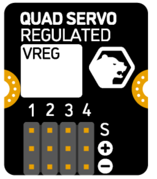
The Quad Servo Module for Yukon, manufactured by Pimoroni, is a versatile control module designed to manage up to four servos simultaneously. It is ideal for robotics, automation projects, and other applications requiring precise control over servo position and speed. This module integrates seamlessly with the Yukon system, offering a compact and efficient solution for servo control.
Explore Projects Built with Quad Servo Module for Yukon
 Open Project in Cirkit Designer
 Open Project in Cirkit Designer
 Open Project in Cirkit Designer
 Open Project in Cirkit Designer
Explore Projects Built with Quad Servo Module for Yukon
Open Project in Cirkit DesignerOpen Project in Cirkit DesignerOpen Project in Cirkit DesignerOpen Project in Cirkit DesignerCommon Applications
- Robotics (e.g., robotic arms, walking robots)
- Automation systems
- Remote-controlled vehicles
- Animatronics and motion control
- Educational projects involving servo motors
Technical Specifications
The Quad Servo Module for Yukon is engineered to provide reliable and precise control for up to four servos. Below are the key technical details:
General Specifications
| Parameter | Value |
|---|---|
| Manufacturer | Pimoroni |
| Number of Servo Outputs | 4 |
| Input Voltage Range | 5V to 12V |
| Signal Voltage | 3.3V (logic level) |
| Maximum Servo Current | 2A per channel (8A total) |
| Communication Protocol | I2C |
| Dimensions | 65mm x 25mm x 10mm |
Pin Configuration
The Quad Servo Module features a straightforward pin layout for easy integration. Below is the pin configuration:
| Pin Name | Description |
|---|---|
| VIN | Power input (5V to 12V) for servos |
| GND | Ground connection |
| SDA | I2C data line |
| SCL | I2C clock line |
| Servo 1-4 | PWM signal outputs for controlling servos |
Usage Instructions
The Quad Servo Module for Yukon is designed for ease of use. Follow the steps below to integrate it into your project:
Connecting the Module
- Power Supply: Connect a 5V to 12V power source to the
VINpin. Ensure the power supply can handle the total current required by all connected servos. - Ground: Connect the
GNDpin to the ground of your system. - I2C Communication: Connect the
SDAandSCLpins to the corresponding I2C pins on your microcontroller or Yukon baseboard. - Servo Connections: Attach up to four servos to the
Servo 1,Servo 2,Servo 3, andServo 4pins.
Controlling the Servos
The module uses I2C communication to control the servos. Below is an example of how to control the servos using an Arduino UNO:
#include <Wire.h>

// I2C address of the Quad Servo Module
#define QUAD_SERVO_ADDR 0x40

void setup() {
  Wire.begin(); // Initialize I2C communication
  Serial.begin(9600); // Initialize serial communication for debugging

  // Example: Set Servo 1 to 90 degrees
  setServoPosition(1, 90);
}

void loop() {
  // Example: Sweep Servo 2 from 0 to 180 degrees
  for (int angle = 0; angle <= 180; angle += 10) {
    setServoPosition(2, angle);
    delay(500); // Wait for half a second
  }
}

// Function to set the position of a servo
void setServoPosition(int servo, int angle) {
  if (servo < 1 || servo > 4) {
    Serial.println("Error: Servo number must be between 1 and 4.");
    return;
  }
  if (angle < 0 || angle > 180) {
    Serial.println("Error: Angle must be between 0 and 180 degrees.");
    return;
  }

  Wire.beginTransmission(QUAD_SERVO_ADDR);
  Wire.write(servo); // Specify the servo number (1-4)
  Wire.write(angle); // Specify the angle (0-180 degrees)
  Wire.endTransmission();

  Serial.print("Servo ");
  Serial.print(servo);
  Serial.print(" set to ");
  Serial.print(angle);
  Serial.println(" degrees.");
}
Best Practices
- Use a stable power supply to avoid voltage drops that could affect servo performance.
- Ensure the total current draw of all servos does not exceed the module's maximum rating (8A).
- Use appropriate servo models that match the voltage and current capabilities of the module.
- Avoid sudden, large movements of multiple servos simultaneously to prevent power surges.
Troubleshooting and FAQs
Common Issues
Servos Not Moving
- Cause: Incorrect wiring or insufficient power supply.
- Solution: Double-check all connections and ensure the power supply meets the voltage and current requirements.
Erratic Servo Movement
- Cause: Noise or interference on the I2C lines.
- Solution: Use shorter wires for I2C connections and add pull-up resistors if necessary.
Overheating
- Cause: Excessive current draw from servos.
- Solution: Ensure the total current draw does not exceed 8A. Use servos with lower current requirements if needed.
I2C Communication Failure
- Cause: Incorrect I2C address or wiring.
- Solution: Verify the I2C address of the module and ensure proper connections to the SDA and SCL pins.
FAQs
Q: Can I use this module with a Raspberry Pi?
A: Yes, the module supports I2C communication, which is compatible with Raspberry Pi. Use the appropriate GPIO pins for SDA and SCL.
Q: What happens if I connect more than four servos?
A: The module is designed to control up to four servos. Connecting additional servos may result in erratic behavior or damage to the module.
Q: Can I power the servos directly from the Arduino?
A: No, servos typically require more current than an Arduino can provide. Use an external power supply connected to the VIN pin.
Q: How do I change the I2C address of the module?
A: Refer to the manufacturer's documentation for instructions on changing the I2C address, if supported.
By following this documentation, you can effectively integrate and use the Quad Servo Module for Yukon in your projects.