Cirkit Designer
Your all-in-one circuit design IDE
Home /
Component Documentation
How to Use ESP32-C6-DEV-KIT-N8-M: Examples, Pinouts, and Specs
Introduction
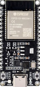
The ESP32-C6-DEV-KIT-N8-M is a development board manufactured by Waveshare, featuring the ESP32-C6 microcontroller. This microcontroller includes Wi-Fi 6, Bluetooth 5, and IEEE 802.15.4 connectivity, making it ideal for IoT applications. The board offers multiple GPIOs, ADCs, and other peripherals, providing a versatile platform for a wide range of project developments.
Explore Projects Built with ESP32-C6-DEV-KIT-N8-M
ESP32-Based Smart Agriculture System with LoRa Communication

This circuit features an ESP32 Devkit V1 microcontroller as the central processing unit, interfacing with various sensors including a PH Meter, an NPK Soil Sensor, and a Soil Moisture Sensor for environmental data collection. It also includes an EBYTE LoRa E220 module for wireless communication. Power management is handled by a Step Up Boost Power Converter, which is connected to a 12V Battery, stepping up the voltage to power the ESP32 and sensors, with common ground connections throughout the circuit.
ESP32-Based GPS Tracker with SD Card Logging and Barometric Sensor

This circuit features an ESP32 Wroom Dev Kit as the main microcontroller, interfaced with an MPL3115A2 sensor for pressure and temperature readings, and a Neo 6M GPS module for location tracking. The ESP32 is also connected to an SD card reader for data logging purposes. A voltage regulator is used to step down the USB power supply to 3.3V, which powers the ESP32, the sensor, and the SD card reader.
ESP32-Based Environmental Monitoring and Alert System with Solar Charging

This circuit features an ESP32 Devkit V1 microcontroller connected to various sensors and modules for monitoring and communication purposes. It includes an MQ-2 gas sensor and a DHT11 temperature and humidity sensor, both interfaced with the ESP32 for environmental data collection. The circuit is powered by a 12V battery, regulated to 5V by step-down converters, and includes a solar charge controller connected to a solar panel for battery charging, a UPS module for power management, and a SIM900A module for GSM communication. Additionally, there is a WS2812 RGB LED strip for visual feedback and a piezo buzzer for audio alerts, both controlled by the ESP32.
ESP32-Based GPS Tracker with Serial Communication
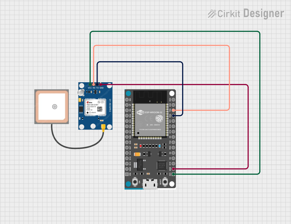
This circuit connects a GPS NEO 6M module to an ESP32 Devkit V1 microcontroller. The ESP32 powers the GPS module and communicates with it via serial connection, using its RX0 and TX0 pins to receive and transmit data. The embedded code on the ESP32 is configured to read GPS data such as latitude, longitude, and altitude, and output this information to the serial monitor.
Explore Projects Built with ESP32-C6-DEV-KIT-N8-M
ESP32-Based Smart Agriculture System with LoRa Communication
This circuit features an ESP32 Devkit V1 microcontroller as the central processing unit, interfacing with various sensors including a PH Meter, an NPK Soil Sensor, and a Soil Moisture Sensor for environmental data collection. It also includes an EBYTE LoRa E220 module for wireless communication. Power management is handled by a Step Up Boost Power Converter, which is connected to a 12V Battery, stepping up the voltage to power the ESP32 and sensors, with common ground connections throughout the circuit.
ESP32-Based GPS Tracker with SD Card Logging and Barometric Sensor
This circuit features an ESP32 Wroom Dev Kit as the main microcontroller, interfaced with an MPL3115A2 sensor for pressure and temperature readings, and a Neo 6M GPS module for location tracking. The ESP32 is also connected to an SD card reader for data logging purposes. A voltage regulator is used to step down the USB power supply to 3.3V, which powers the ESP32, the sensor, and the SD card reader.
ESP32-Based Environmental Monitoring and Alert System with Solar Charging
This circuit features an ESP32 Devkit V1 microcontroller connected to various sensors and modules for monitoring and communication purposes. It includes an MQ-2 gas sensor and a DHT11 temperature and humidity sensor, both interfaced with the ESP32 for environmental data collection. The circuit is powered by a 12V battery, regulated to 5V by step-down converters, and includes a solar charge controller connected to a solar panel for battery charging, a UPS module for power management, and a SIM900A module for GSM communication. Additionally, there is a WS2812 RGB LED strip for visual feedback and a piezo buzzer for audio alerts, both controlled by the ESP32.
ESP32-Based GPS Tracker with Serial Communication
This circuit connects a GPS NEO 6M module to an ESP32 Devkit V1 microcontroller. The ESP32 powers the GPS module and communicates with it via serial connection, using its RX0 and TX0 pins to receive and transmit data. The embedded code on the ESP32 is configured to read GPS data such as latitude, longitude, and altitude, and output this information to the serial monitor.
Common Applications and Use Cases
- IoT Devices: Smart home systems, industrial IoT, and wearable technology.
- Wireless Communication: Wi-Fi and Bluetooth-based projects.
- Sensor Networks: Environmental monitoring, health monitoring systems.
- Prototyping and Development: Rapid prototyping for embedded systems and electronics projects.
Technical Specifications
Key Technical Details
| Specification | Value |
|---|---|
| Microcontroller | ESP32-C6 |
| Wi-Fi | Wi-Fi 6 (802.11ax) |
| Bluetooth | Bluetooth 5 |
| IEEE 802.15.4 | Supported |
| Operating Voltage | 3.3V |
| Input Voltage | 5V (via USB) |
| GPIO Pins | 30 |
| ADC Channels | 12-bit, 18 channels |
| Flash Memory | 8MB |
| SRAM | 512KB |
| Communication | UART, SPI, I2C, I2S, CAN, Ethernet |
| Dimensions | 54mm x 25mm |
Pin Configuration and Descriptions
| Pin Number | Pin Name | Description |
|---|---|---|
| 1 | GND | Ground |
| 2 | 3V3 | 3.3V Power Supply |
| 3 | EN | Enable Pin |
| 4 | IO0 | GPIO0, ADC1_CH0, Touch0 |
| 5 | IO1 | GPIO1, ADC1_CH1, Touch1 |
| 6 | IO2 | GPIO2, ADC1_CH2, Touch2 |
| 7 | IO3 | GPIO3, ADC1_CH3, Touch3 |
| 8 | IO4 | GPIO4, ADC1_CH4, Touch4 |
| 9 | IO5 | GPIO5, ADC1_CH5, Touch5 |
| 10 | IO6 | GPIO6, ADC1_CH6, Touch6 |
| 11 | IO7 | GPIO7, ADC1_CH7, Touch7 |
| 12 | IO8 | GPIO8, ADC1_CH8, Touch8 |
| 13 | IO9 | GPIO9, ADC1_CH9, Touch9 |
| 14 | IO10 | GPIO10, ADC1_CH10, Touch10 |
| 15 | IO11 | GPIO11, ADC1_CH11, Touch11 |
| 16 | IO12 | GPIO12, ADC1_CH12, Touch12 |
| 17 | IO13 | GPIO13, ADC1_CH13, Touch13 |
| 18 | IO14 | GPIO14, ADC1_CH14, Touch14 |
| 19 | IO15 | GPIO15, ADC1_CH15, Touch15 |
| 20 | IO16 | GPIO16, ADC1_CH16, Touch16 |
| 21 | IO17 | GPIO17, ADC1_CH17, Touch17 |
| 22 | IO18 | GPIO18, ADC1_CH18, Touch18 |
| 23 | IO19 | GPIO19, ADC1_CH19, Touch19 |
| 24 | IO20 | GPIO20, ADC1_CH20, Touch20 |
| 25 | IO21 | GPIO21, ADC1_CH21, Touch21 |
| 26 | IO22 | GPIO22, ADC1_CH22, Touch22 |
| 27 | IO23 | GPIO23, ADC1_CH23, Touch23 |
| 28 | IO24 | GPIO24, ADC1_CH24, Touch24 |
| 29 | IO25 | GPIO25, ADC1_CH25, Touch25 |
| 30 | IO26 | GPIO26, ADC1_CH26, Touch26 |
Usage Instructions
How to Use the Component in a Circuit
Powering the Board:
- Connect the board to a 5V power supply via the USB port.
- Ensure the 3.3V pin is used for any external components requiring 3.3V.
Connecting to GPIOs:
- Use the GPIO pins for digital input/output operations.
- Configure the pins in your code as needed (e.g., input, output, ADC).
Programming the Board:
- Use the Arduino IDE or ESP-IDF to program the ESP32-C6.
- Select the appropriate board and port in the IDE.
Important Considerations and Best Practices
- Voltage Levels: Ensure all connected components operate at 3.3V to avoid damaging the board.
- Pin Multiplexing: Be aware of the multiple functions of each pin (e.g., ADC, Touch) and configure them appropriately in your code.
- Heat Management: The board may heat up during operation; ensure proper ventilation.
Example Code for Arduino IDE
// Example code to blink an LED connected to GPIO2

void setup() {
  // Initialize GPIO2 as an output pin
  pinMode(2, OUTPUT);
}

void loop() {
  // Turn the LED on
  digitalWrite(2, HIGH);
  delay(1000); // Wait for 1 second

  // Turn the LED off
  digitalWrite(2, LOW);
  delay(1000); // Wait for 1 second
}
Troubleshooting and FAQs
Common Issues Users Might Face
Board Not Detected by IDE:
- Ensure the correct board and port are selected in the IDE.
- Check the USB connection and try a different cable or port.
Wi-Fi Connection Issues:
- Verify the Wi-Fi credentials in your code.
- Ensure the Wi-Fi network is within range and operational.
GPIO Not Responding:
- Check the pin configuration in your code.
- Ensure there are no short circuits or incorrect connections.
Solutions and Tips for Troubleshooting
- Reset the Board: Press the reset button on the board to restart it.
- Check Power Supply: Ensure the board is receiving adequate power (5V via USB).
- Update Drivers: Ensure you have the latest USB drivers installed for your operating system.
- Consult Documentation: Refer to the ESP32-C6 datasheet and Waveshare documentation for detailed information.
By following this documentation, users can effectively utilize the ESP32-C6-DEV-KIT-N8-M for their IoT and embedded system projects, leveraging its advanced connectivity and versatile GPIO options.