How to Use LED Tactile Button Breakout v10: Examples, Pinouts, and Specs
Introduction
The LED Tactile Button Breakout v1.0 is a compact and versatile electronic component that integrates a tactile pushbutton switch with an embedded LED. This combination allows for a convenient user interface component with both input (button press) and output (LED illumination) capabilities. It is commonly used in electronic projects for initiating actions, user input, and providing visual feedback.
Explore Projects Built with LED Tactile Button Breakout v10

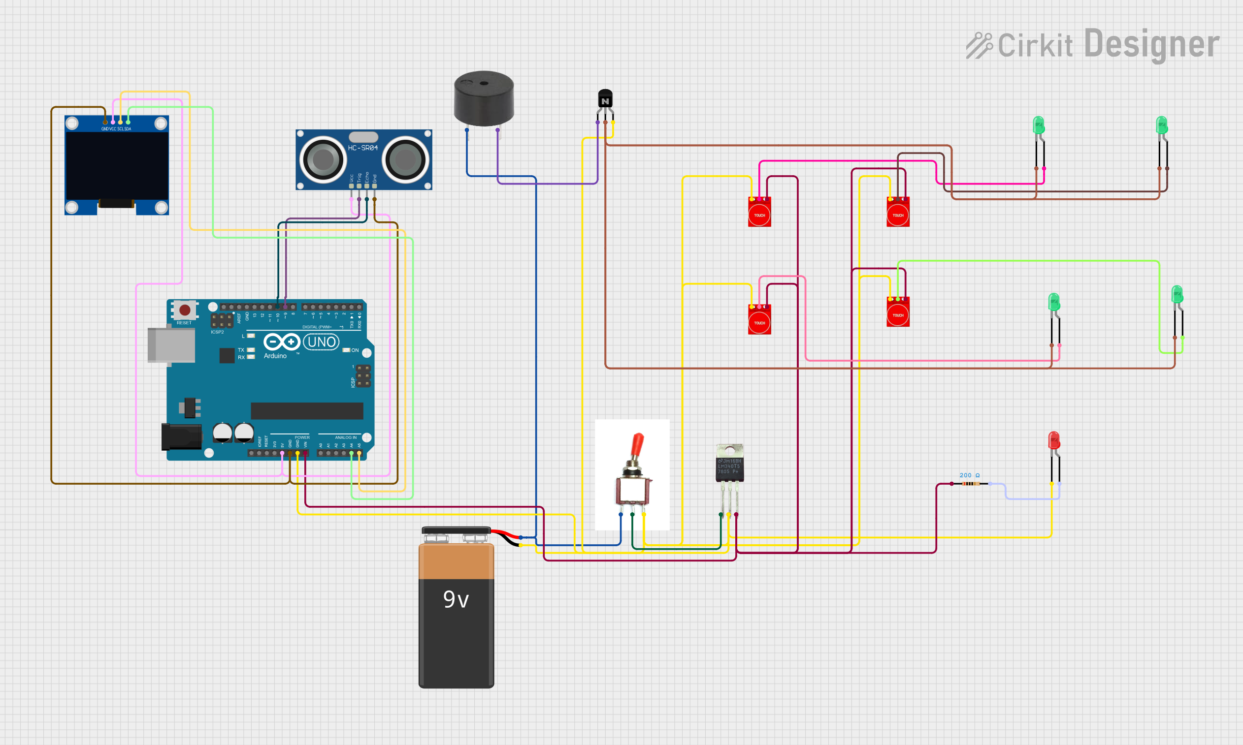
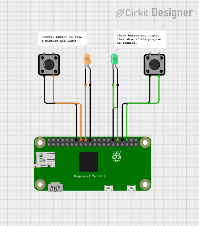

Explore Projects Built with LED Tactile Button Breakout v10
Common Applications and Use Cases
- User interfaces for microcontroller projects
- Interactive displays and control panels
- Prototyping and educational kits
- DIY electronics and hobbyist projects
Technical Specifications
Key Technical Details
- Voltage: Typically 3.3V to 5V for LED operation
- Current: LED current typically 20mA, button contact rated for 50mA
- Power Ratings: Dependent on LED color and usage
- Switch Bounce Time: <10ms
- LED Wavelength/Color: Dependent on model (e.g., Red, Green, Blue)
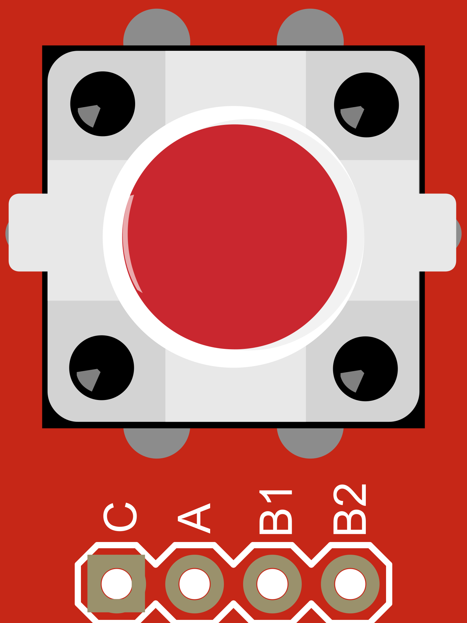
Pin Configuration and Descriptions
| Pin Number | Description | Notes |
|---|---|---|
| 1 | LED Anode (+) | Connect to V+ through a resistor |
| 2 | Button Output | Goes LOW when button is pressed |
| 3 | Button Ground (-) | Connect to ground |
| 4 | LED Cathode (-) | Connect to ground |
Usage Instructions
How to Use the Component in a Circuit
Connecting the LED:
- Connect pin 1 (LED Anode) to a digital output pin on your microcontroller through a current-limiting resistor.
- Connect pin 4 (LED Cathode) to the ground.
Connecting the Button:
- Connect pin 2 (Button Output) to a digital input pin on your microcontroller.
- Enable the internal pull-up resistor on the microcontroller or use an external pull-up resistor.
- Connect pin 3 (Button Ground) to the ground.
Calculating the Current-Limiting Resistor for the LED:
- Use Ohm's Law:
R = (V_supply - V_led) / I_led - Where
V_supplyis the supply voltage,V_ledis the LED forward voltage, andI_ledis the desired current through the LED (typically 20mA).
- Use Ohm's Law:
Important Considerations and Best Practices
- Always use a current-limiting resistor for the LED to prevent damage.
- Ensure the supply voltage does not exceed the maximum rating for the LED.
- Debounce the button either in hardware with a capacitor or in software to prevent false triggering.
- Avoid applying force to the button that exceeds its mechanical limits.
Example Code for Arduino UNO
// Define the pin connections
const int buttonPin = 2; // Button output connected to digital pin 2
const int ledPin = 3;    // LED anode connected to digital pin 3 through a resistor

void setup() {
  pinMode(buttonPin, INPUT_PULLUP); // Enable internal pull-up resistor
  pinMode(ledPin, OUTPUT);          // Set the LED pin as an output
}

void loop() {
  // Check if the button is pressed (button output goes LOW)
  if (digitalRead(buttonPin) == LOW) {
    digitalWrite(ledPin, HIGH); // Turn on the LED
  } else {
    digitalWrite(ledPin, LOW);  // Turn off the LED
  }
}
Troubleshooting and FAQs
Common Issues Users Might Face
- LED not lighting up: Check the polarity of the LED pins and ensure the current-limiting resistor is correctly calculated and installed.
- Button not responding: Verify the button pins are correctly connected and the internal pull-up resistor is enabled.
- Unstable button state: Implement software debouncing or add a hardware debounce circuit.
Solutions and Tips for Troubleshooting
- Double-check all connections against the pin configuration table.
- Measure the voltage across the LED to ensure it is within the specified range.
- Use a multimeter to check the continuity of the button when pressed.
- If using long wires, ensure there is no significant voltage drop that could affect the LED brightness or button functionality.
FAQs
Q: Can I use this component with a 3.3V system? A: Yes, the LED Tactile Button Breakout v1.0 can typically be used with a 3.3V system, but ensure the LED forward voltage is compatible.
Q: What size resistor do I need for the LED? A: The resistor value depends on your supply voltage and the LED's forward voltage and current. Use the Ohm's Law formula provided in the usage instructions to calculate the appropriate value.
Q: How can I debounce the button in software? A: Implement a delay after detecting a button press or use a state-change detection algorithm to ignore noise.
Q: Is it possible to control the brightness of the LED? A: Yes, you can use Pulse Width Modulation (PWM) on the LED pin to control the brightness.
This documentation provides a comprehensive guide to using the LED Tactile Button Breakout v1.0. For further assistance or technical support, please refer to the manufacturer's resources or community forums.