How to Use TFT ST7789V 2.8': Examples, Pinouts, and Specs
Introduction
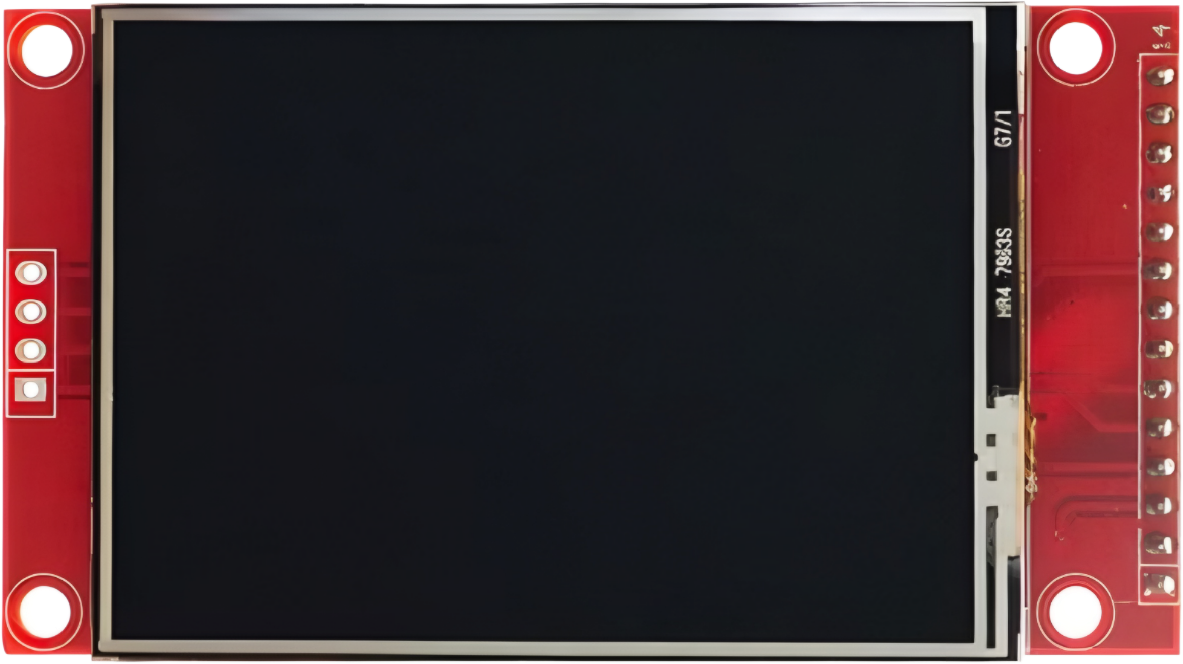
The TFT ST7789V 2.8' is a 2.8-inch thin-film transistor (TFT) display module that utilizes the ST7789V driver. This display is known for its high resolution, vibrant color depth, and compact size, making it ideal for a wide range of embedded applications. It is commonly used in projects requiring graphical user interfaces, such as IoT devices, handheld instruments, and portable displays.
Explore Projects Built with TFT ST7789V 2.8'


Explore Projects Built with TFT ST7789V 2.8'
Common Applications
- Smart home devices (e.g., thermostats, control panels)
- Wearable technology
- Portable gaming consoles
- Industrial control systems
- Educational and hobbyist projects with microcontrollers (e.g., Arduino, Raspberry Pi)
Technical Specifications
Below are the key technical details and pin configuration for the TFT ST7789V 2.8' display module:
Key Technical Details
| Parameter | Value |
|---|---|
| Display Type | TFT LCD |
| Driver IC | ST7789V |
| Screen Size | 2.8 inches |
| Resolution | 240 x 320 pixels |
| Color Depth | 16-bit (65,536 colors) |
| Interface | SPI (Serial Peripheral Interface) |
| Operating Voltage | 3.3V |
| Backlight Voltage | 3.0V to 3.3V |
| Backlight Current | ~20mA |
| Operating Temperature | -20°C to 70°C |
| Viewing Angle | 80° (all directions) |
Pin Configuration
The TFT ST7789V 2.8' module typically has the following pinout:
| Pin Number | Pin Name | Description |
|---|---|---|
| 1 | GND | Ground |
| 2 | VCC | Power supply (3.3V) |
| 3 | SCL | Serial Clock (SPI clock input) |
| 4 | SDA | Serial Data (SPI data input) |
| 5 | RES | Reset pin (active low) |
| 6 | DC | Data/Command control pin |
| 7 | CS | Chip Select (active low) |
| 8 | BLK | Backlight control (connect to 3.3V for always on) |
Usage Instructions
How to Use the Component in a Circuit
- Power Supply: Connect the
VCCpin to a 3.3V power source and theGNDpin to ground. - SPI Communication: Connect the
SCL(clock) andSDA(data) pins to the corresponding SPI pins on your microcontroller. - Control Pins:
- Connect the
RESpin to a GPIO pin on your microcontroller for resetting the display. - Use the
DCpin to toggle between data and command modes. - Connect the
CSpin to a GPIO pin to enable or disable the display.
- Connect the
- Backlight: Connect the
BLKpin to 3.3V for constant backlight or to a PWM pin for brightness control.
Important Considerations
- Ensure the operating voltage is strictly 3.3V to avoid damaging the display.
- Use level shifters if your microcontroller operates at 5V logic levels.
- Keep SPI connections as short as possible to minimize signal degradation.
- Add decoupling capacitors near the power pins for stable operation.
Example Code for Arduino UNO
Below is an example of how to interface the TFT ST7789V 2.8' with an Arduino UNO using the Adafruit ST7789 library:
#include <Adafruit_GFX.h>    // Core graphics library
#include <Adafruit_ST7789.h> // ST7789 driver library
#include <SPI.h>             // SPI library

// Define pin connections
#define TFT_CS    10  // Chip select pin
#define TFT_RST   9   // Reset pin
#define TFT_DC    8   // Data/Command pin

// Initialize the display object
Adafruit_ST7789 tft = Adafruit_ST7789(TFT_CS, TFT_DC, TFT_RST);

void setup() {
  // Initialize serial communication for debugging
  Serial.begin(9600);
  Serial.println("TFT ST7789V Test");

  // Initialize the display
  tft.init(240, 320); // Initialize with 240x320 resolution
  tft.setRotation(1); // Set display orientation (1 = landscape)

  // Fill the screen with a color
  tft.fillScreen(ST77XX_BLACK);

  // Draw a simple rectangle
  tft.fillRect(50, 50, 140, 100, ST77XX_RED);

  // Display text
  tft.setTextColor(ST77XX_WHITE);
  tft.setTextSize(2);
  tft.setCursor(60, 80);
  tft.print("Hello, World!");
}

void loop() {
  // Nothing to do here
}
Notes:
- Install the Adafruit GFX and Adafruit ST7789 libraries via the Arduino Library Manager before running the code.
- Adjust the pin definitions (
TFT_CS,TFT_RST,TFT_DC) to match your wiring.
Troubleshooting and FAQs
Common Issues
No Display Output:
- Verify all connections, especially power and SPI pins.
- Ensure the
CSpin is correctly toggled to enable the display. - Check if the backlight (
BLKpin) is powered.
Flickering or Unstable Display:
- Use shorter wires for SPI connections to reduce noise.
- Add decoupling capacitors near the power supply pins.
Incorrect Colors or Artifacts:
- Ensure the SPI clock speed is within the display's supported range.
- Verify that the
DCpin is correctly toggled between data and command modes.
Display Not Resetting:
- Confirm that the
RESpin is connected to a GPIO pin and is toggled during initialization.
- Confirm that the
FAQs
Q: Can I use this display with a 5V microcontroller?
A: Yes, but you must use level shifters to convert 5V logic to 3.3V logic for the SPI and control pins.
Q: How do I control the backlight brightness?
A: Connect the BLK pin to a PWM-capable GPIO pin on your microcontroller and adjust the duty cycle to control brightness.
Q: Can I use this display with Raspberry Pi?
A: Yes, the display is compatible with Raspberry Pi. Use the SPI interface and appropriate libraries (e.g., luma.lcd or ST7789 Python libraries).
Q: What is the maximum SPI clock speed supported?
A: The ST7789V driver typically supports SPI clock speeds up to 15 MHz. Check your specific module's datasheet for exact details.