How to Use Motor Driver: Examples, Pinouts, and Specs
Introduction
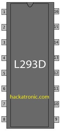
The L293D chip by Sharvi Electronics is a widely used motor driver that allows for the control of the speed and direction of motors in various applications. It is an integrated circuit that can control two DC motors simultaneously in any direction, making it ideal for robotics, automotive applications, and small electric vehicles.
Explore Projects Built with Motor Driver

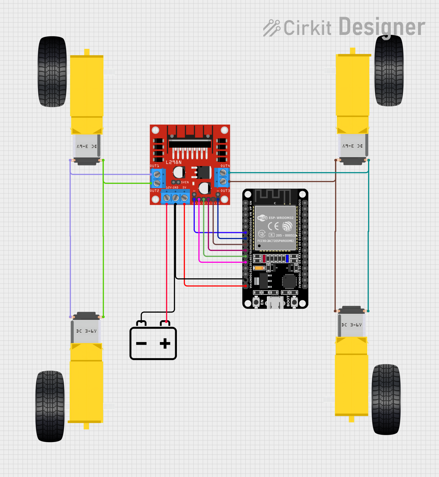


Explore Projects Built with Motor Driver
Common Applications and Use Cases
- Robotics: Steering and propulsion systems.
- Automotive: Control of small DC motors for automation.
- Hobby Projects: DIY projects involving motor control, such as RC cars.
- Educational: Learning about motor control in electronics courses.
Technical Specifications
Key Technical Details
- Supply Voltage (Vcc1): 4.5V to 36V
- Logic Supply Voltage (Vcc2): 4.5V to 7V
- Output Current (each channel): 600mA
- Peak Output Current (each channel): 1.2A
- Power Dissipation: 4W
Pin Configuration and Descriptions
| Pin Number | Name | Description |
|---|---|---|
| 1 | 1,2EN | Enables outputs for Motor 1 when high |
| 2 | 1A | Input 1 for Motor 1 |
| 3 | 1Y | Output 1 for Motor 1 |
| 4 | GND | Ground (0V) |
| 5 | GND | Ground (0V) |
| 6 | 2Y | Output 2 for Motor 1 |
| 7 | 2A | Input 2 for Motor 1 |
| 8 | Vcc2 | Logic Supply Voltage |
| 9 | 3,4EN | Enables outputs for Motor 2 when high |
| 10 | 3A | Input 1 for Motor 2 |
| 11 | 3Y | Output 1 for Motor 2 |
| 12 | GND | Ground (0V) |
| 13 | GND | Ground (0V) |
| 14 | 4Y | Output 2 for Motor 2 |
| 15 | 4A | Input 2 for Motor 2 |
| 16 | Vcc1 | Motor Supply Voltage |
Usage Instructions
How to Use the L293D in a Circuit
- Connect Vcc1 (Pin 16) to your motor power supply, which should be within 4.5V to 36V.
- Connect Vcc2 (Pin 8) to your logic power supply, which should be within 4.5V to 7V.
- Connect the ground pins (Pins 4, 5, 12, 13) to the ground of your power supply.
- Connect the enable pins (1,2EN and 3,4EN) to a digital output on your microcontroller if you wish to control the enable state through software, or tie them high to Vcc2 to keep the motors enabled.
- Connect the input pins (1A, 2A for Motor 1 and 3A, 4A for Motor 2) to digital outputs on your microcontroller.
- Connect the output pins (1Y, 2Y for Motor 1 and 3Y, 4Y for Motor 2) to the terminals of your DC motors.
Important Considerations and Best Practices
- Always use a decoupling capacitor (typically 0.1uF to 1uF) near the power pins of the L293D to filter out noise and prevent voltage spikes.
- Do not exceed the recommended voltage and current ratings to avoid damaging the L293D chip.
- Use heat sinks if operating near the peak current ratings to dissipate heat and prevent thermal shutdown.
- Ensure that the motors' power requirements are compatible with the L293D's output current capabilities.
Troubleshooting and FAQs
Common Issues
- Motor not running: Check if the enable pins are high and inputs are correctly configured.
- Overheating: Ensure proper heat sinking and that the current does not exceed the peak ratings.
- Inconsistent motor operation: Verify connections and check for loose wires or solder joints.
Solutions and Tips for Troubleshooting
- Double-check wiring against the pin configuration table.
- Use a multimeter to verify the voltage levels at the power pins and the logic inputs.
- If using PWM to control speed, ensure the frequency is within the L293D's operating range.
FAQs
Q: Can I control stepper motors with the L293D? A: Yes, the L293D can be used to control bipolar stepper motors with the correct sequencing of inputs.
Q: What is the maximum frequency for PWM control with the L293D? A: The L293D can typically handle PWM frequencies up to a few kHz.
Q: Can I use the L293D without a microcontroller? A: Yes, you can manually control the inputs with switches, but a microcontroller allows for more precise and programmable control.
Example Arduino UNO Code
// Define the L293D connections to the Arduino
const int motor1Pin1 = 2; // Input 1 for Motor 1
const int motor1Pin2 = 3; // Input 2 for Motor 1
const int enableMotor1 = 9; // Enable Pin for Motor 1

void setup() {
  // Set the motor control pins as outputs
  pinMode(motor1Pin1, OUTPUT);
  pinMode(motor1Pin2, OUTPUT);
  pinMode(enableMotor1, OUTPUT);

  // Enable the motor
  digitalWrite(enableMotor1, HIGH);
}

void loop() {
  // Spin the motor in one direction
  digitalWrite(motor1Pin1, HIGH);
  digitalWrite(motor1Pin2, LOW);
  delay(2000);

  // Stop the motor
  digitalWrite(motor1Pin1, LOW);
  digitalWrite(motor1Pin2, LOW);
  delay(1000);

  // Spin the motor in the opposite direction
  digitalWrite(motor1Pin1, LOW);
  digitalWrite(motor1Pin2, HIGH);
  delay(2000);

  // Stop the motor
  digitalWrite(motor1Pin1, LOW);
  digitalWrite(motor1Pin2, LOW);
  delay(1000);
}
This example demonstrates basic forward and reverse control of a DC motor using the L293D motor driver connected to an Arduino UNO. The enableMotor1 pin is kept high to enable the motor, and the motor1Pin1 and motor1Pin2 pins are alternated between high and low to change the direction of the motor.