How to Use Reed Switch: Examples, Pinouts, and Specs

Introduction
A Reed Switch is an electromechanical component that operates as an electrical switch when exposed to a magnetic field. It is composed of two ferromagnetic metal contacts (reeds) enclosed within a glass tube, which is filled with an inert gas to prevent corrosion and ensure a long operational life. The contacts are normally open and close when a magnetic field is applied, making the reed switch a useful component for sensing magnetic presence, counting, or as a safety interlock device.
Explore Projects Built with Reed Switch
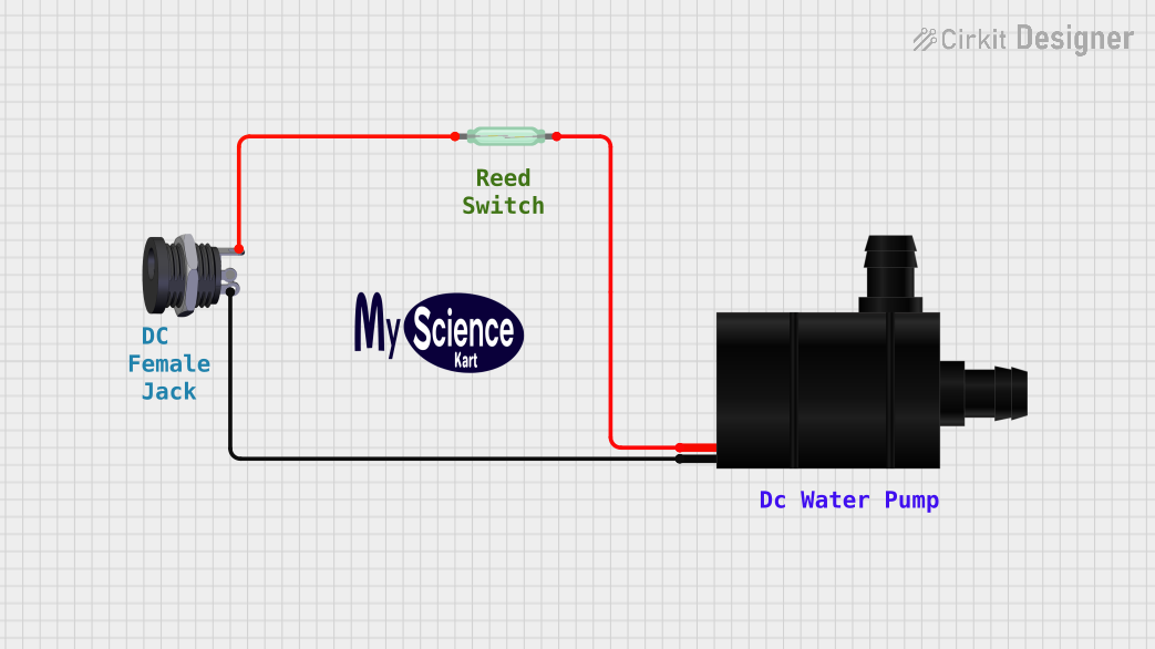
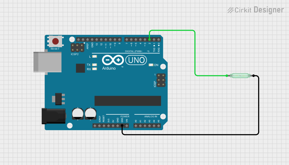
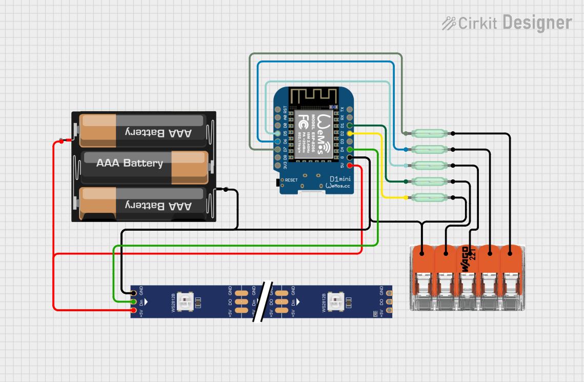
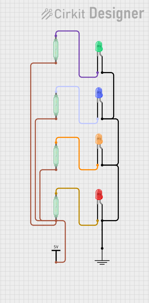
Explore Projects Built with Reed Switch
Common Applications and Use Cases
- Magnetic door and window sensors for security systems
- Proximity detection in consumer electronics
- Position and speed sensing in automotive applications
- Reed relays for switching high voltages or currents
- Liquid level and flow meters
Technical Specifications
Key Technical Details
- Switch Type: Normally open (contacts close in presence of magnetic field)
- Contact Rating: Typically 10W to 100W (varies by model)
- Switching Voltage: Up to 1000V (model dependent)
- Switching Current: Up to 1A (model dependent)
- Operate Time: Typically 0.5ms to 1ms
- Release Time: Typically 0.1ms to 0.5ms
- Contact Resistance: Typically less than 100 milliohms
- Insulation Resistance: Typically greater than 10^9 ohms
Pin Configuration and Descriptions
| Pin Number | Description |
|---|---|
| 1 | Contact 1 (Reed 1) |
| 2 | Contact 2 (Reed 2) |
Note: The reed switch is a two-terminal device with no polarity, so the pin numbers are for identification purposes only.
Usage Instructions
How to Use the Reed Switch in a Circuit
- Connection: Connect one terminal of the reed switch to the input of a sensing circuit and the other terminal to a common ground or positive supply, depending on the circuit design.
- Magnetic Actuation: Place a magnet near the reed switch to close the contacts. The magnet's orientation and strength are critical for reliable operation.
- Debouncing: Although reed switches have fast operate and release times, consider using a debouncing circuit or software to ensure clean signal transitions.
Important Considerations and Best Practices
- Magnetic Interference: Keep other magnetic sources away from the reed switch to prevent unintended operation.
- Glass Enclosure: Handle with care as the glass enclosure is fragile.
- Contact Rating: Do not exceed the voltage and current ratings to avoid damaging the switch.
- Mounting: Secure the reed switch firmly to prevent movement that could affect operation.
Troubleshooting and FAQs
Common Issues
- Intermittent Operation: Check for proper magnet alignment and strength. Ensure there are no nearby magnetic interference sources.
- No Operation: Verify that the reed switch is not damaged and that the circuit connections are secure.
- Contact Sticking: This can occur if the switch is subjected to a higher current or voltage than specified. Replace the switch if necessary.
Solutions and Tips for Troubleshooting
- Testing: Use a multimeter to check for continuity when the magnet is near the reed switch.
- Magnet Positioning: Adjust the position of the magnet for optimal operation.
- Circuit Inspection: Look for any signs of damage or loose connections in the circuit.
FAQs
Q: Can a reed switch be used to switch AC loads?
- A: Yes, but ensure the switch's ratings are suitable for the AC voltage and current.
Q: How can I extend the life of a reed switch?
- A: Avoid exceeding the rated current and voltage, and minimize mechanical shock and vibration.
Q: Is there a polarity to be observed when connecting a reed switch?
- A: No, reed switches are non-polarized and can be connected in any orientation.
Example Code for Arduino UNO
Below is an example code snippet for using a reed switch with an Arduino UNO. The code will print a message to the Serial Monitor when the reed switch is activated by a magnet.
// Define the pin connected to the reed switch
const int reedPin = 2;

void setup() {
  // Initialize the reedPin as an input
  pinMode(reedPin, INPUT_PULLUP);
  // Begin serial communication at 9600 baud rate
  Serial.begin(9600);
}

void loop() {
  // Read the state of the reed switch
  int state = digitalRead(reedPin);

  // Check if the reed switch is closed (magnet is in proximity)
  if (state == LOW) {
    // Print message to the Serial Monitor
    Serial.println("Magnet detected!");
  }

  // Small delay to debounce and prevent multiple messages
  delay(50);
}
Note: The INPUT_PULLUP mode is used to enable the internal pull-up resistor, which ensures a default high state when the switch is open.