How to Use Bus TFT Module: Examples, Pinouts, and Specs
Introduction
A Bus TFT Module is a display component that utilizes thin-film transistor (TFT) technology to deliver high-quality visual output. It is designed to provide vibrant colors, sharp images, and fast refresh rates, making it an excellent choice for applications requiring detailed graphical displays. These modules are commonly used in devices such as smartphones, tablets, industrial control panels, and embedded systems. Their ability to interface with microcontrollers and microprocessors makes them versatile for a wide range of projects.
Explore Projects Built with Bus TFT Module


Explore Projects Built with Bus TFT Module
Technical Specifications
Below are the key technical details of a typical Bus TFT Module. Note that specifications may vary depending on the specific model.
General Specifications
- Display Type: TFT (Thin-Film Transistor) LCD
- Resolution: 320x240 pixels (QVGA) or higher
- Color Depth: 16-bit or 24-bit (65K or 16M colors)
- Interface: Parallel Bus (8-bit, 16-bit, or 24-bit)
- Operating Voltage: 3.3V (logic) / 5V (backlight)
- Backlight: LED with adjustable brightness
- Viewing Angle: Typically 160° horizontal and vertical
- Touchscreen: Optional (Resistive or Capacitive)
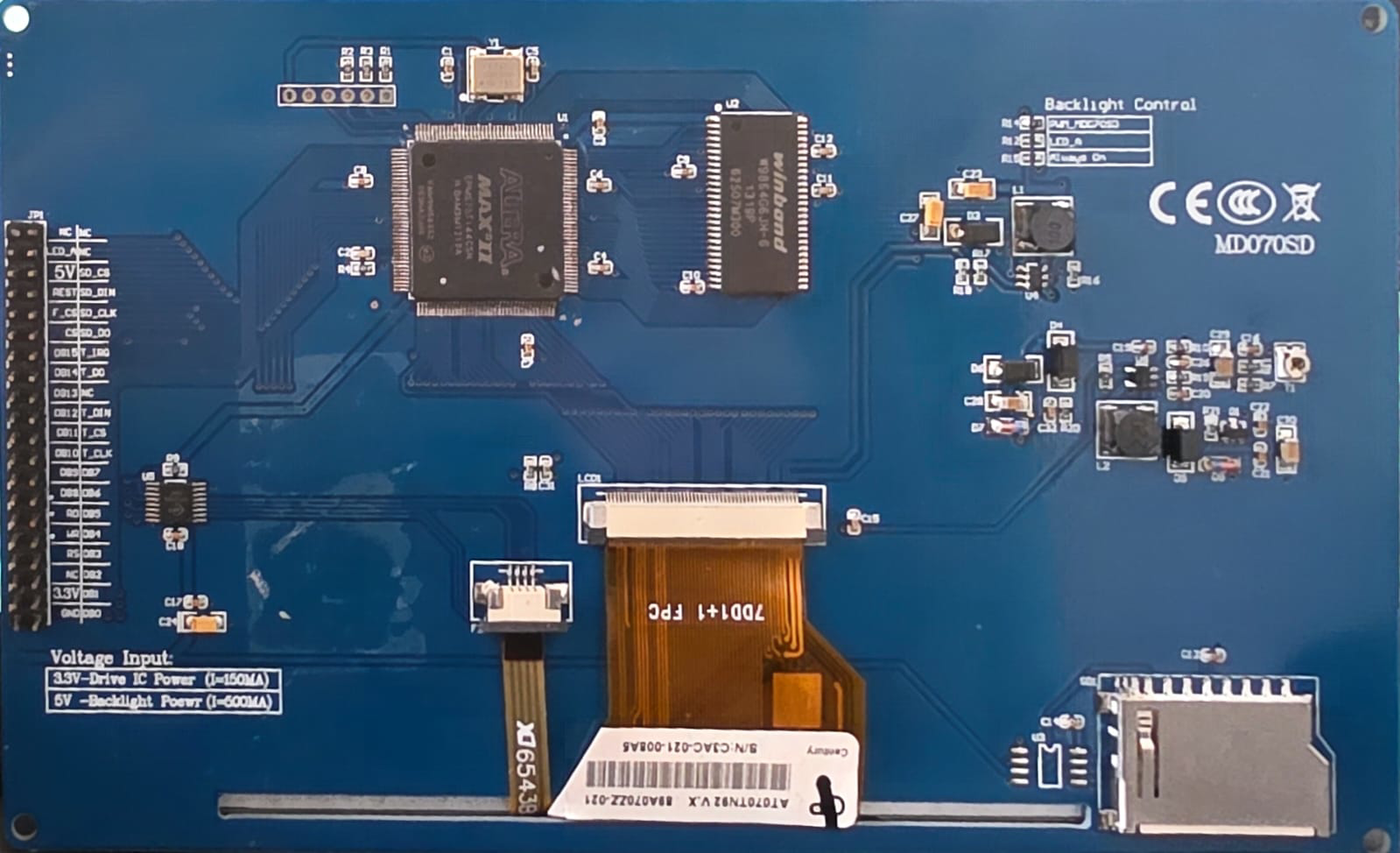
Pin Configuration
The Bus TFT Module typically has a set of pins for power, data, and control. Below is a common pin configuration:
| Pin Name | Description | Direction |
|---|---|---|
| VCC | Power supply for the module (3.3V) | Input |
| GND | Ground connection | Input |
| DB0-DB15 | Data bus pins (8/16-bit mode) | Input/Output |
| RS (DC) | Register Select (Data/Command) | Input |
| WR | Write signal | Input |
| RD | Read signal | Input |
| CS | Chip Select | Input |
| RESET | Reset signal | Input |
| BL | Backlight control | Input |
| T_IRQ | Touchscreen interrupt (if present) | Output |
| T_CS | Touchscreen chip select (if present) | Input |
Usage Instructions
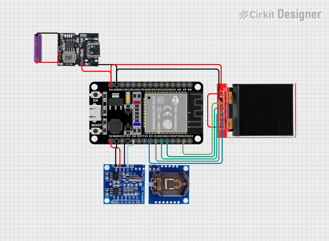
Connecting the Bus TFT Module
- Power Supply: Connect the VCC pin to a 3.3V power source and the GND pin to ground. If the module has a 5V backlight, ensure the backlight pin (BL) is connected to a 5V source.
- Data Bus: Connect the DB0-DB15 pins to the corresponding data pins on your microcontroller or microprocessor. For 8-bit mode, only DB0-DB7 are used.
- Control Pins: Connect the RS, WR, RD, CS, and RESET pins to GPIO pins on your microcontroller. These pins control the module's operation.
- Backlight: If the module supports backlight control, connect the BL pin to a PWM-capable GPIO pin for brightness adjustment.
- Touchscreen (Optional): If the module includes a touchscreen, connect the T_IRQ and T_CS pins to GPIO pins on your microcontroller.
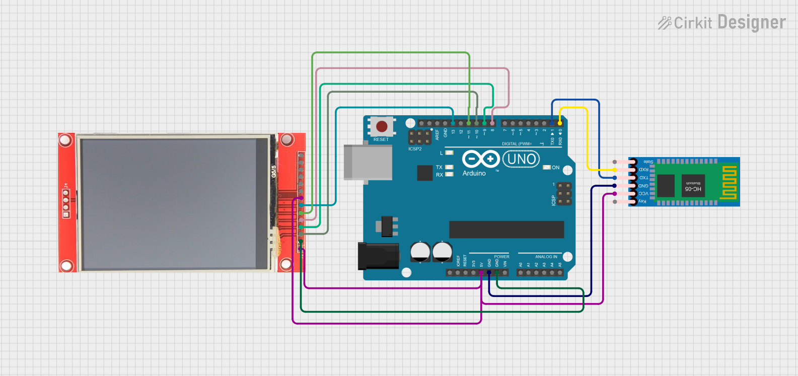
Example: Using with Arduino UNO
Below is an example of how to use a Bus TFT Module with an Arduino UNO. This example assumes an 8-bit data bus and uses the Adafruit_GFX and Adafruit_TFTLCD libraries.
#include <Adafruit_GFX.h>      // Core graphics library
#include <Adafruit_TFTLCD.h>  // Hardware-specific library for TFT

// Define pin connections for the TFT module
#define LCD_CS A3  // Chip Select
#define LCD_CD A2  // Command/Data
#define LCD_WR A1  // Write
#define LCD_RD A0  // Read
#define LCD_RESET A4  // Reset

// Create an instance of the TFT library
Adafruit_TFTLCD tft(LCD_CS, LCD_CD, LCD_WR, LCD_RD, LCD_RESET);

void setup() {
  tft.reset();  // Reset the display
  tft.begin(0x9341);  // Initialize with the display driver ID (e.g., ILI9341)

  tft.fillScreen(0x0000);  // Clear the screen (black)
  tft.setCursor(0, 0);     // Set cursor to top-left corner
  tft.setTextColor(0xFFFF); // Set text color (white)
  tft.setTextSize(2);      // Set text size
  tft.println("Hello, TFT!");  // Display text
}

void loop() {
  // Add your code here to update the display
}
Best Practices
- Use level shifters if your microcontroller operates at 5V logic levels, as most TFT modules require 3.3V logic.
- Avoid touching the display surface to prevent smudges or damage.
- Use decoupling capacitors near the power pins to reduce noise.
- Ensure proper grounding to avoid display flickering or instability.
Troubleshooting and FAQs
Common Issues
Display Not Turning On:
- Check the power connections (VCC and GND).
- Verify that the backlight pin (BL) is connected properly.
No Image or Incorrect Colors:
- Ensure the data bus pins (DB0-DB15) are connected correctly.
- Verify the initialization code matches the display driver (e.g., ILI9341).
Touchscreen Not Responding:
- Check the T_IRQ and T_CS connections.
- Ensure the touchscreen library is included and initialized properly.
Flickering or Noise:
- Add decoupling capacitors near the power pins.
- Ensure all ground connections are secure.
FAQs
Q: Can I use a Bus TFT Module with a 5V microcontroller?
A: Yes, but you will need level shifters to convert the 5V logic signals to 3.3V.
Q: How do I adjust the brightness of the backlight?
A: Connect the BL pin to a PWM-capable GPIO pin and use PWM to control the brightness.
Q: What is the difference between 8-bit and 16-bit modes?
A: In 8-bit mode, only DB0-DB7 are used, reducing the number of required pins but lowering data transfer speed. In 16-bit mode, all DB0-DB15 pins are used for faster data transfer.
Q: Can I use this module without a touchscreen?
A: Yes, the touchscreen functionality is optional and does not affect the display operation.