
How to Use uPesy Wroom DevKit V2: Examples, Pinouts, and Specs
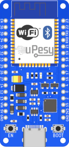
 Design with uPesy Wroom DevKit V2 in Cirkit Designer
Introduction
The uPesy Wroom DevKit V2 is a versatile development kit built around the ESP32-WROOM-32 module. Designed for Internet of Things (IoT) applications, this board provides robust Wi-Fi and Bluetooth connectivity, making it ideal for smart devices, home automation, and wireless sensor networks. With its compact design and multiple GPIO pins, the DevKit V2 is perfect for prototyping and integrating with various sensors, actuators, and other peripherals.
Explore Projects Built with uPesy Wroom DevKit V2
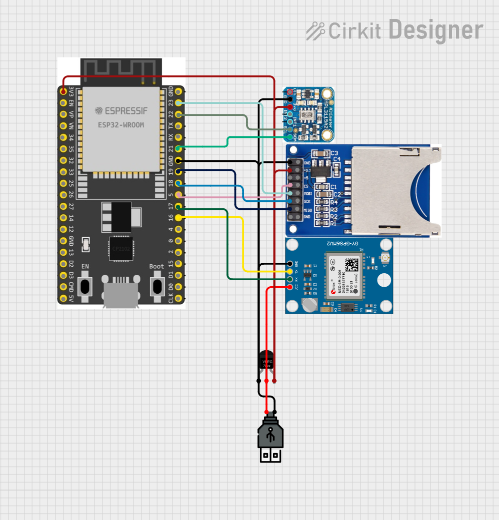
 Open Project in Cirkit Designer
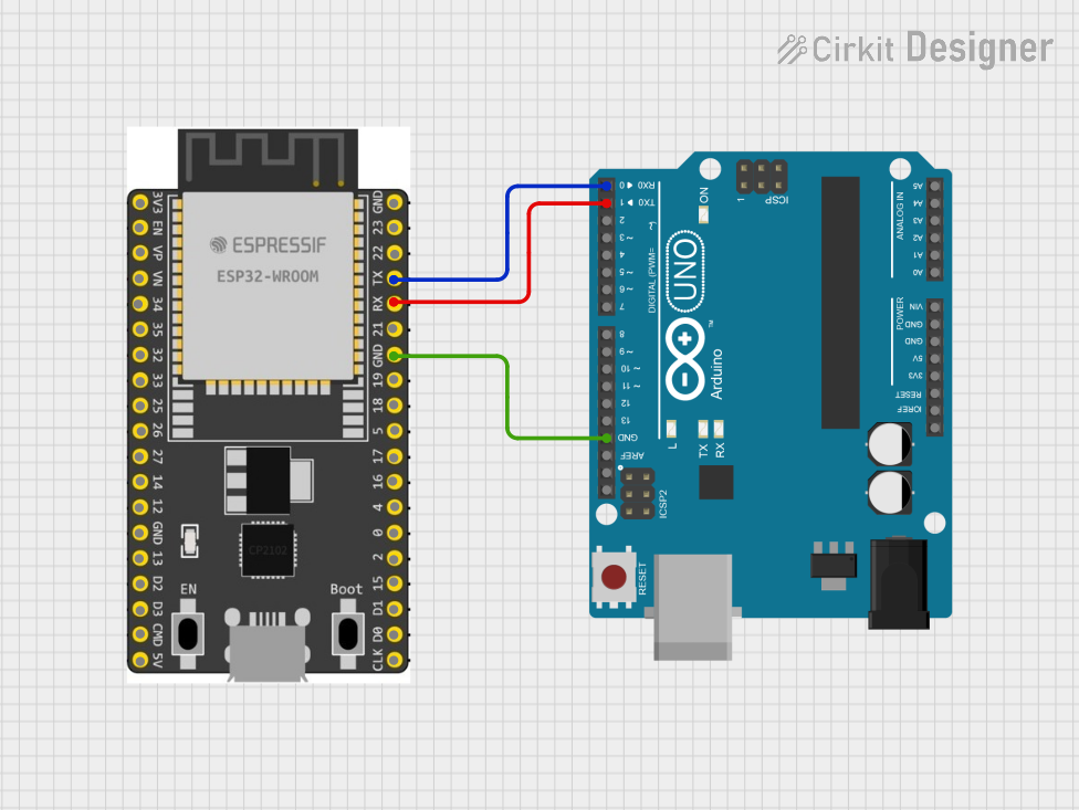
 Open Project in Cirkit Designer
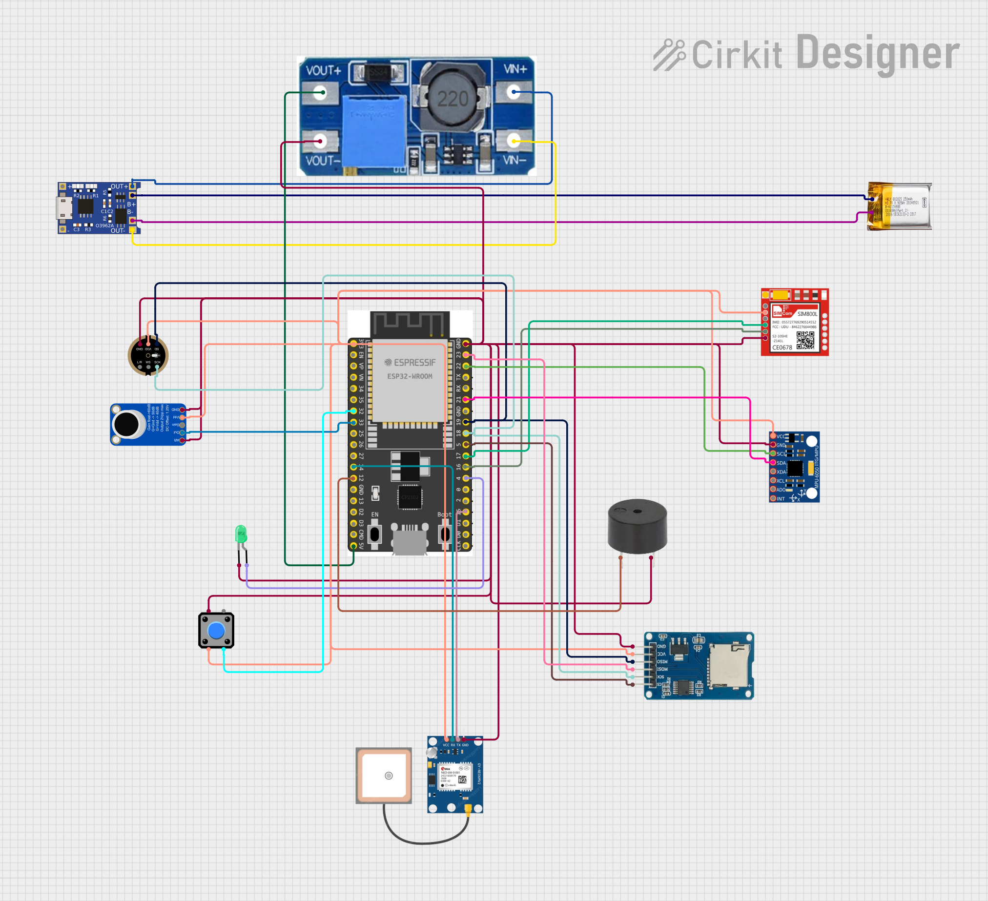
 Open Project in Cirkit Designer
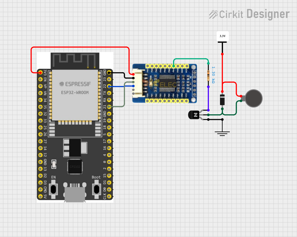
 Open Project in Cirkit Designer
Explore Projects Built with uPesy Wroom DevKit V2

 Open Project in Cirkit Designer
 Open Project in Cirkit Designer
 Open Project in Cirkit Designer
 Open Project in Cirkit Designer
Common Applications and Use Cases
- IoT devices and smart home systems
- Wireless sensor networks
- Remote monitoring and control
- Robotics and automation
- Wearable technology
- Educational projects and prototyping
Technical Specifications
The following table outlines the key technical details of the uPesy Wroom DevKit V2:
| Parameter | Specification |
|---|---|
| Microcontroller | ESP32-WROOM-32 |
| Wireless Connectivity | Wi-Fi 802.11 b/g/n, Bluetooth v4.2 (BLE) |
| Operating Voltage | 3.3V |
| Input Voltage (VIN) | 5V (via USB) |
| Flash Memory | 4MB |
| SRAM | 520KB |
| GPIO Pins | 30 (including ADC, DAC, PWM, I2C, SPI, UART) |
| Analog Input Pins | 18 (12-bit ADC resolution) |
| Digital I/O Pins | 30 |
| PWM Channels | 16 |
| DAC Channels | 2 |
| Clock Speed | 240 MHz |
| USB Interface | Micro-USB |
| Dimensions | 54mm x 25mm |
Pin Configuration and Descriptions
The uPesy Wroom DevKit V2 features a 30-pin layout. Below is a summary of the pin configuration:
| Pin Name | Type | Description |
|---|---|---|
| VIN | Power Input | 5V input for powering the board via external source |
| GND | Ground | Ground pin |
| 3V3 | Power Output | 3.3V regulated output |
| EN | Enable | Enables or disables the module |
| GPIO0-GPIO39 | Digital I/O | General-purpose input/output pins |
| ADC1-ADC18 | Analog Input | 12-bit ADC channels for analog signals |
| DAC1, DAC2 | Analog Output | Digital-to-analog converter pins |
| TXD0, RXD0 | UART | UART communication pins |
| SCL, SDA | I2C | I2C clock and data lines |
| SCK, MISO, MOSI | SPI | SPI communication pins |
| BOOT | Boot Mode | Used for flashing firmware |
Usage Instructions
How to Use the Component in a Circuit
Powering the Board:
- Connect the board to a computer or USB power source using a Micro-USB cable.
- Alternatively, supply 5V to the VIN pin and connect GND to the ground of your power source.
Programming the Board:
- Install the ESP32 board package in the Arduino IDE or use the ESP-IDF framework for advanced development.
- Select the correct board (
ESP32 Dev Module) and port in the Arduino IDE.
Connecting Peripherals:
- Use the GPIO pins to interface with sensors, actuators, or other devices.
- Ensure that the voltage levels of connected peripherals are compatible with the 3.3V logic of the ESP32.
Flashing Firmware:
- Hold the BOOT button while pressing the EN button to enter flashing mode.
- Upload your code using the Arduino IDE or other compatible tools.
Important Considerations and Best Practices
- Voltage Levels: Avoid applying voltages higher than 3.3V to the GPIO pins to prevent damage.
- Power Supply: Ensure a stable power supply to avoid unexpected resets or malfunctions.
- Heat Management: The ESP32 can get warm during operation; ensure proper ventilation if used in enclosed spaces.
- Pull-up/Pull-down Resistors: Use appropriate resistors for GPIO pins configured as inputs to avoid floating states.
Example Code for Arduino UNO Integration
Below is an example of how to use the uPesy Wroom DevKit V2 to read a temperature sensor and send the data over Wi-Fi:
#include <WiFi.h> // Include the Wi-Fi library

// Replace with your network credentials
const char* ssid = "Your_SSID";
const char* password = "Your_PASSWORD";

void setup() {
  Serial.begin(115200); // Initialize serial communication at 115200 baud
  WiFi.begin(ssid, password); // Connect to Wi-Fi network

  // Wait for connection
  while (WiFi.status() != WL_CONNECTED) {
    delay(1000);
    Serial.println("Connecting to Wi-Fi...");
  }
  Serial.println("Connected to Wi-Fi!");
}

void loop() {
  // Example: Read a sensor value (e.g., analog pin A0)
  int sensorValue = analogRead(34); // Replace 34 with your ADC pin
  Serial.print("Sensor Value: ");
  Serial.println(sensorValue);

  delay(1000); // Wait for 1 second before reading again
}
Troubleshooting and FAQs
Common Issues Users Might Face
Board Not Detected by Computer:
- Ensure the correct USB drivers are installed for the ESP32.
- Try a different USB cable or port.
Wi-Fi Connection Fails:
- Double-check the SSID and password.
- Ensure the Wi-Fi network is within range and operational.
Code Upload Fails:
- Verify that the correct board and port are selected in the Arduino IDE.
- Hold the BOOT button while uploading the code.
GPIO Pins Not Responding:
- Check for proper connections and ensure the pins are not damaged.
- Confirm that the pins are correctly configured in the code.
Solutions and Tips for Troubleshooting
- Use a multimeter to verify power supply voltages and continuity of connections.
- Update the ESP32 board package in the Arduino IDE to the latest version.
- Refer to the ESP32 datasheet for detailed information on pin functions and electrical characteristics.
- If the board becomes unresponsive, try resetting it by pressing the EN button.
By following this documentation, users can effectively utilize the uPesy Wroom DevKit V2 for a wide range of IoT and embedded applications.