How to Use ULTRASONIC RANGING: Examples, Pinouts, and Specs
Introduction
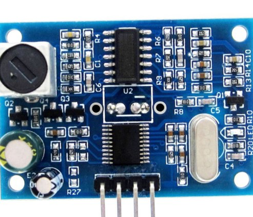
The JSN-SR04M-2 is an ultrasonic ranging module manufactured by SUNLEPHANT. This component is designed to measure distances by emitting ultrasonic waves and detecting the time it takes for the echoes to return. It is widely used in robotics, obstacle avoidance systems, distance measurement applications, and various automation projects.
Explore Projects Built with ULTRASONIC RANGING
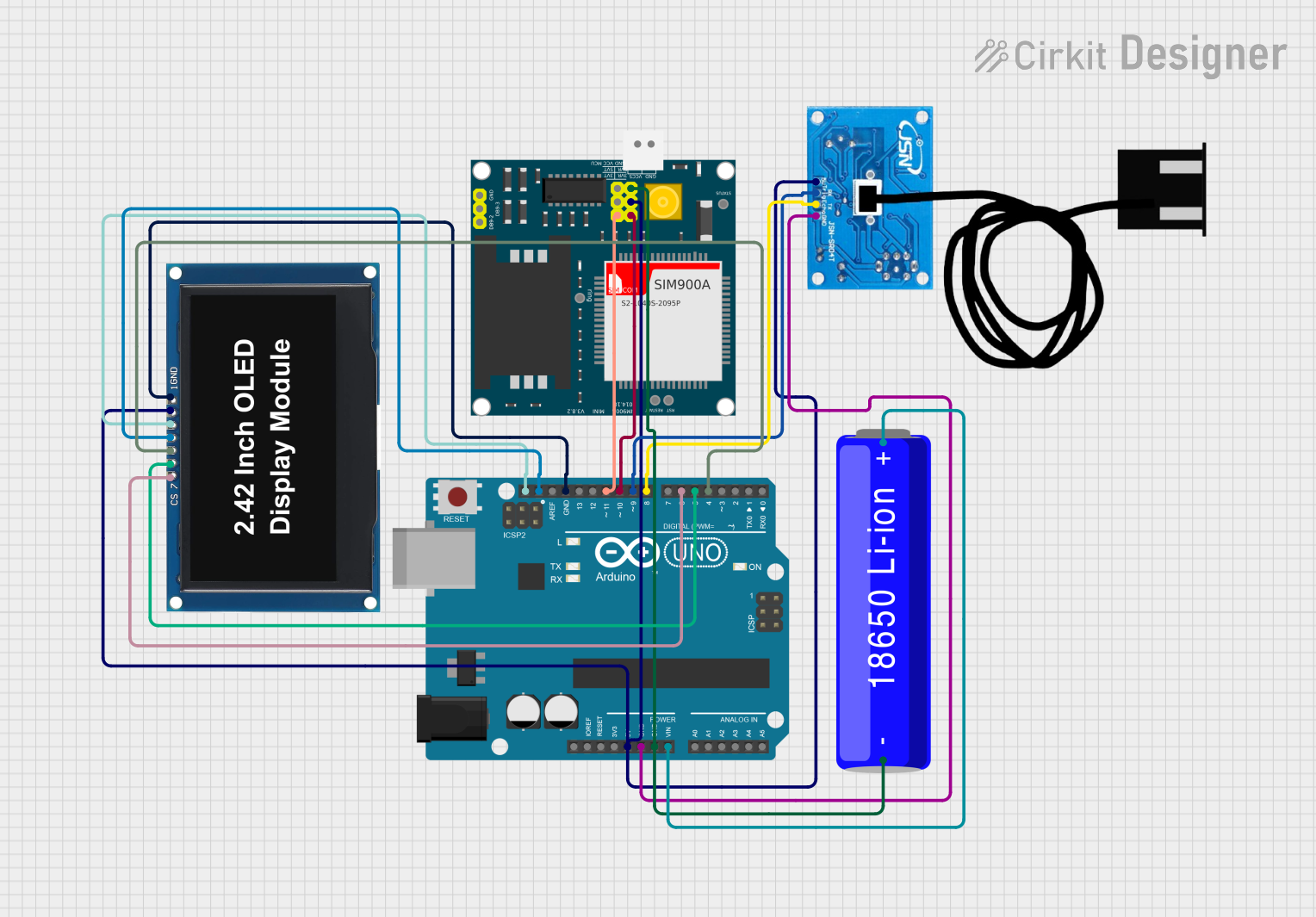
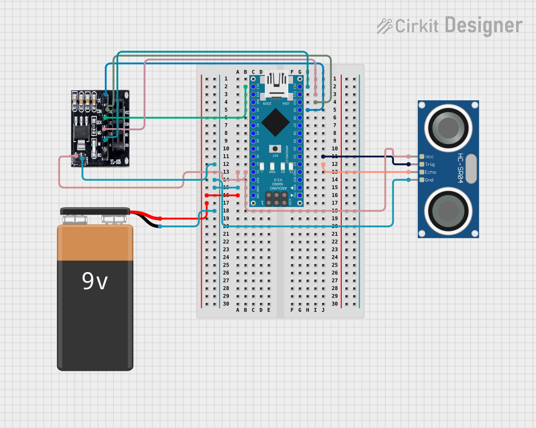
Explore Projects Built with ULTRASONIC RANGING
Common Applications and Use Cases
- Robotics for object detection and avoidance
- Measuring distances in industrial environments
- Parking sensors for vehicles
- Level control in tanks or silos
- DIY projects involving distance measurement or proximity sensing
Technical Specifications
Key Technical Details
- Operating Voltage: 3.3V to 5V DC
- Quiescent Current: <2mA
- Operating Current: 15mA
- Acoustic Emission Frequency: 40kHz
- Max Range: 4.5m
- Min Range: 25cm
- Resolution: 0.3cm
- Measuring Angle: 75 degrees
- Operating Temperature: -20°C to +70°C
Pin Configuration and Descriptions
| Pin Number | Pin Name | Description |
|---|---|---|
| 1 | VCC | Power supply (3.3V to 5V DC) |
| 2 | Trig | Trigger input (TTL pulse) |
| 3 | Echo | Echo output (TTL level signal) |
| 4 | GND | Ground |
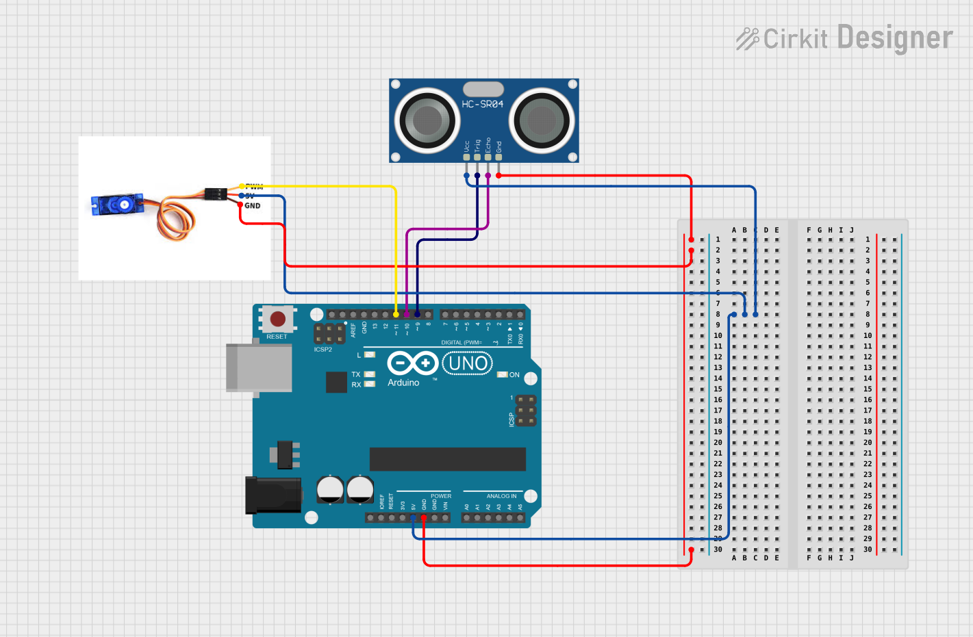
Usage Instructions
How to Use the Component in a Circuit
- Connect the VCC pin to a 3.3V or 5V power supply.
- Connect the GND pin to the ground of the power supply.
- The Trig pin should be connected to a digital output pin on the microcontroller.
- The Echo pin should be connected to a digital input pin on the microcontroller.
Important Considerations and Best Practices
- Ensure that the power supply is stable and within the specified voltage range.
- Avoid physical obstructions in front of the sensor within the minimum range.
- Use a pull-up resistor if necessary on the Echo pin to ensure proper logic level reading.
- Keep the module away from noisy electrical environments to prevent false readings.
Example Code for Arduino UNO
// Define the connection pins
const int trigPin = 9;
const int echoPin = 10;

void setup() {
  // Initialize serial communication
  Serial.begin(9600);
  // Define pin modes
  pinMode(trigPin, OUTPUT);
  pinMode(echoPin, INPUT);
}

void loop() {
  // Clear the trigPin by setting it LOW
  digitalWrite(trigPin, LOW);
  delayMicroseconds(2);

  // Set the trigPin HIGH for 10 microseconds to send the ultrasonic pulse
  digitalWrite(trigPin, HIGH);
  delayMicroseconds(10);
  digitalWrite(trigPin, LOW);

  // Read the echoPin; pulseIn returns the duration in microseconds
  long duration = pulseIn(echoPin, HIGH);

  // Calculate the distance in centimeters
  long distance = duration * 0.034 / 2;

  // Print the distance on the Serial Monitor
  Serial.print("Distance: ");
  Serial.print(distance);
  Serial.println(" cm");

  // Delay between measurements
  delay(500);
}
Troubleshooting and FAQs
Common Issues Users Might Face
- Inaccurate Readings: Ensure there are no obstacles or sound-absorbing materials in front of the sensor that could affect the readings.
- No Readings: Check the power supply and wiring connections. Ensure the Trig and Echo pins are connected correctly.
- Intermittent Readings: This could be due to electrical noise. Try adding a capacitor across the power supply pins close to the module.
Solutions and Tips for Troubleshooting
- Always test the module in a controlled environment before deploying it in the field.
- Use twisted pair cables for Trig and Echo pins to reduce susceptibility to electrical noise.
- If the module is being used outdoors, protect it from the elements, such as water or dust.
FAQs
Q: Can the JSN-SR04M-2 be used to detect non-solid objects, like liquids? A: The module is designed for solid objects. It may not give reliable readings for liquids due to their varying density and surface reflectivity.
Q: What is the maximum distance the JSN-SR04M-2 can measure? A: The maximum range is 4.5 meters under ideal conditions.
Q: Is it possible to use multiple JSN-SR04M-2 modules in one project? A: Yes, but ensure that the ultrasonic signals from one module do not interfere with another by staggering the trigger signals.
Q: How can I extend the range of the module? A: The range cannot be extended beyond the specified maximum range. However, ensuring a clear path and minimal interference can help achieve the best possible range within the specified limits.