
How to Use ESC 4in1 25A: Examples, Pinouts, and Specs
 Design with ESC 4in1 25A in Cirkit Designer
Introduction
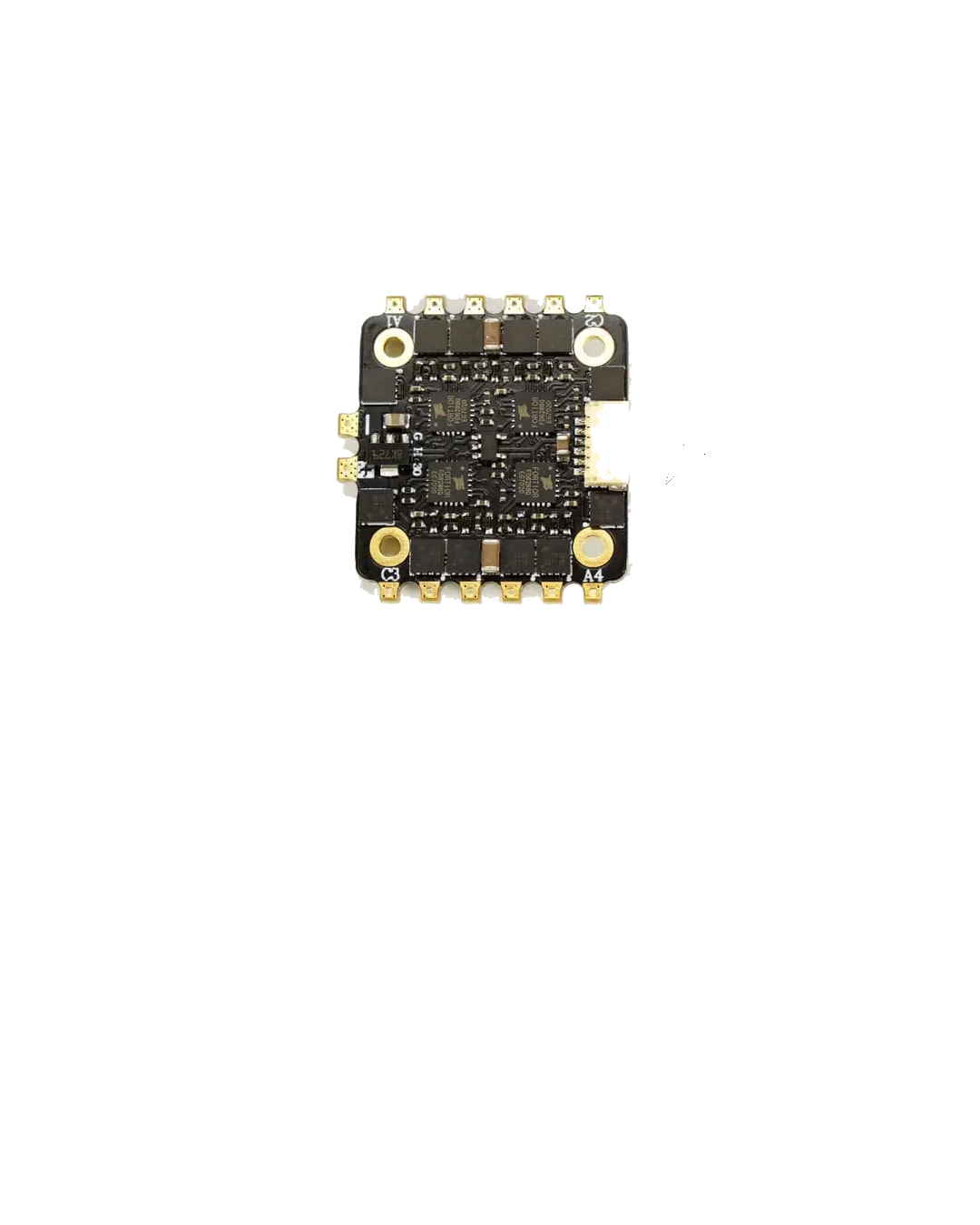
The ESC 4in1 25A is an advanced Electronic Speed Controller designed to simplify the control of brushless motors in multirotors and RC vehicles. By integrating four ESC channels into a single compact unit, it reduces wiring complexity and weight, making it ideal for drones, quadcopters, and other multirotor platforms. With a maximum current rating of 25A per channel, this ESC is capable of handling high-performance motors while maintaining efficiency and reliability.
Explore Projects Built with ESC 4in1 25A
 Open Project in Cirkit Designer
 Open Project in Cirkit Designer
 Open Project in Cirkit Designer
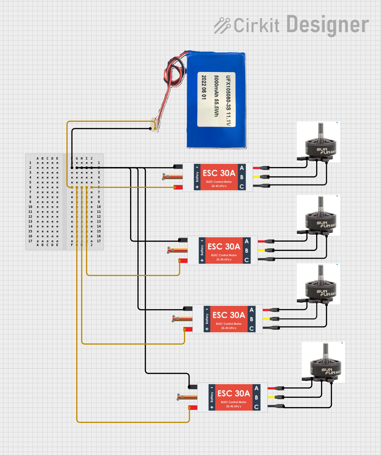 Open Project in Cirkit Designer
Explore Projects Built with ESC 4in1 25A
Open Project in Cirkit DesignerOpen Project in Cirkit DesignerOpen Project in Cirkit DesignerOpen Project in Cirkit DesignerCommon Applications and Use Cases
- Multirotor drones (quadcopters, hexacopters, etc.)
- RC vehicles (cars, boats, and planes)
- Robotics projects requiring multiple brushless motors
- Compact designs where space and weight savings are critical
Technical Specifications
The ESC 4in1 25A is built to deliver reliable performance under demanding conditions. Below are its key technical specifications:
| Parameter | Value |
|---|---|
| Input Voltage Range | 2S–6S LiPo (7.4V–22.2V) |
| Maximum Current (per ESC) | 25A continuous, 30A burst (10 sec) |
| Number of Channels | 4 |
| Supported Protocols | PWM, Oneshot125, DShot150/300/600 |
| BEC Output | None |
| Dimensions | 36mm x 36mm |
| Mounting Hole Spacing | 30.5mm x 30.5mm |
| Weight | ~15g |
| Firmware Compatibility | BLHeli_S |
| Motor Type | Brushless (3-phase) |
Pin Configuration and Descriptions
The ESC 4in1 25A features a standard pinout for easy integration into multirotor flight controllers. Below is the pin configuration:
| Pin Name | Description |
|---|---|
| VBAT | Main power input (connect to LiPo battery positive terminal) |
| GND | Ground connection (connect to LiPo battery negative terminal) |
| M1, M2, M3, M4 | Motor outputs for channels 1, 2, 3, and 4 (connect to brushless motors) |
| Signal 1–4 | Signal inputs for channels 1–4 (connect to flight controller motor outputs) |
| Telemetry | Optional telemetry output (provides real-time data such as current and RPM) |
Usage Instructions
How to Use the ESC 4in1 25A in a Circuit
- Power Connection: Connect the VBAT and GND pins to the positive and negative terminals of your LiPo battery, respectively. Ensure the battery voltage is within the supported range (2S–6S).
- Motor Connection: Connect the three wires of each brushless motor to the corresponding motor output pins (M1, M2, M3, M4). If the motor spins in the wrong direction, swap any two wires.
- Signal Connection: Connect the signal inputs (Signal 1–4) to the motor output pins of your flight controller. Ensure the signal protocol (e.g., PWM, DShot) is configured correctly in the flight controller firmware.
- Telemetry (Optional): If your flight controller supports telemetry, connect the telemetry pin to the appropriate input on the flight controller.
Important Considerations and Best Practices
- Cooling: Ensure adequate airflow over the ESC to prevent overheating, especially during high-current operation.
- Firmware Updates: Use BLHeli_S software to update the ESC firmware and configure settings such as motor direction and signal protocol.
- Capacitor Installation: For high-current applications, consider adding a low-ESR capacitor across the VBAT and GND terminals to reduce voltage spikes.
- Signal Protocol: Verify that your flight controller and ESC are using the same signal protocol (e.g., DShot600 for low latency and high precision).
Example Code for Arduino UNO
While the ESC 4in1 25A is typically used with flight controllers, it can also be controlled using an Arduino UNO for testing or custom applications. Below is an example code snippet to control one motor using a PWM signal:
#include <Servo.h> // Include the Servo library for generating PWM signals

Servo esc; // Create a Servo object to control the ESC

void setup() {
  esc.attach(9); // Attach the ESC signal wire to pin 9 on the Arduino
  esc.writeMicroseconds(1000); // Send minimum throttle (1000 µs) to arm the ESC
  delay(5000); // Wait for 5 seconds to ensure the ESC is armed
}

void loop() {
  esc.writeMicroseconds(1500); // Send a throttle signal (1500 µs for 50% throttle)
  delay(5000); // Run the motor at 50% throttle for 5 seconds

  esc.writeMicroseconds(1000); // Send minimum throttle to stop the motor
  delay(5000); // Wait for 5 seconds before repeating
}
Note: Ensure the ESC is properly powered and connected to a brushless motor before running the code. Always test in a safe environment to avoid accidents.
Troubleshooting and FAQs
Common Issues and Solutions
Motors Not Spinning
- Cause: Incorrect signal connection or protocol mismatch.
- Solution: Verify the signal wires are connected to the correct flight controller outputs. Check that the signal protocol is configured correctly in the flight controller firmware.
Overheating
- Cause: Insufficient cooling or excessive current draw.
- Solution: Ensure proper airflow over the ESC. Check that the motors and propellers are not overloading the ESC.
Motor Spins in the Wrong Direction
- Cause: Incorrect motor wiring.
- Solution: Swap any two of the three motor wires to reverse the direction.
ESC Not Arming
- Cause: Throttle signal is not at the minimum value during startup.
- Solution: Ensure the throttle signal is set to 1000 µs (minimum) when powering on the ESC.
FAQs
Can I use the ESC 4in1 25A with a 7S LiPo battery?
- No, the ESC supports a maximum input voltage of 6S (22.2V). Using a 7S battery may damage the ESC.
Does the ESC 4in1 25A have a built-in BEC?
- No, this ESC does not include a BEC. You will need an external BEC or a flight controller with a built-in voltage regulator to power your receiver and other peripherals.
How do I update the firmware?
- Use the BLHeli_S software and a compatible USB linker to update the firmware. Follow the instructions provided in the BLHeli_S documentation.
Can I use this ESC for brushed motors?
- No, the ESC 4in1 25A is designed specifically for brushless motors.
By following this documentation, you can effectively integrate and operate the ESC 4in1 25A in your projects.