
How to Use MCP4725: Examples, Pinouts, and Specs
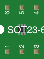
 Design with MCP4725 in Cirkit Designer
Introduction
The MCP4725 is a 12-bit Digital-to-Analog Converter (DAC) manufactured by Microchip Technology. It features an I2C interface, making it simple to integrate into microcontroller-based projects. The MCP4725 is capable of converting digital signals into precise analog voltages, with an output range from 0V to VDD. This component is ideal for applications requiring accurate analog signal generation, such as audio signal processing, waveform generation, and sensor calibration.
Explore Projects Built with MCP4725
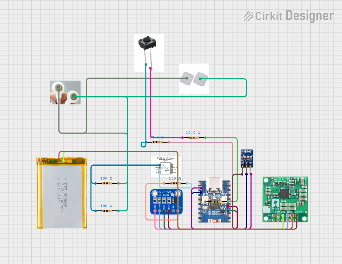 Open Project in Cirkit Designer
 Open Project in Cirkit Designer
 Open Project in Cirkit Designer
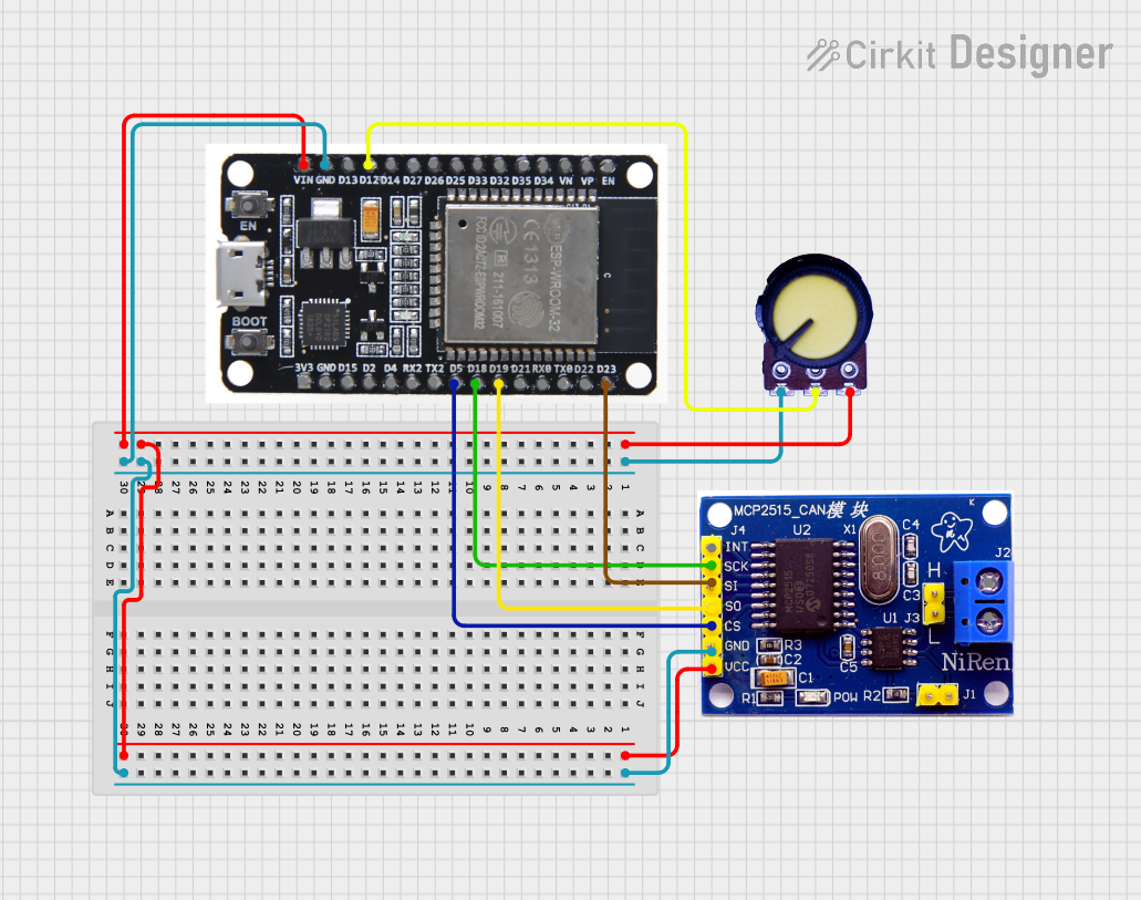 Open Project in Cirkit Designer
Explore Projects Built with MCP4725
Open Project in Cirkit DesignerOpen Project in Cirkit DesignerOpen Project in Cirkit DesignerOpen Project in Cirkit DesignerCommon Applications
- Audio signal generation and processing
- Precision voltage reference for sensors
- Waveform generation in test equipment
- Analog control in industrial systems
- LED dimming and motor control
Technical Specifications
Key Features
- Resolution: 12-bit (4096 steps)
- Interface: I2C (up to 3.4 Mbps in Fast Mode Plus)
- Output Voltage Range: 0V to VDD
- Supply Voltage (VDD): 2.7V to 5.5V
- EEPROM: Non-volatile memory for storing DAC settings
- Output Drive Capability: 25 mA (typical)
- Low Power Consumption: 0.4 mA (typical operating current)
- Temperature Range: -40°C to +125°C
Pin Configuration and Descriptions
The MCP4725 is available in an 8-pin package. Below is the pinout and description:
| Pin Number | Pin Name | Description |
|---|---|---|
| 1 | VDD | Positive power supply (2.7V to 5.5V). |
| 2 | NC | No connection (leave unconnected). |
| 3 | VOUT | Analog output voltage (0V to VDD). |
| 4 | GND | Ground reference. |
| 5 | SCL | I2C clock input. |
| 6 | SDA | I2C data input/output. |
| 7 | A0 | I2C address selection bit (used to set the device address). |
| 8 | NC | No connection (leave unconnected). |
I2C Address
The MCP4725 has a 7-bit I2C address, which is determined by the A0 pin:
- A0 = 0: Default address is
0x60. - A0 = 1: Address becomes
0x61.
Usage Instructions
Connecting the MCP4725
- Power Supply: Connect the VDD pin to a 3.3V or 5V power source, and the GND pin to ground.
- I2C Interface: Connect the SCL and SDA pins to the corresponding I2C pins on your microcontroller. Use pull-up resistors (typically 4.7 kΩ) on the SCL and SDA lines if not already present.
- Analog Output: Connect the VOUT pin to the desired load or circuit where the analog signal is required.
Example Circuit
Below is a typical connection diagram for the MCP4725 with an Arduino UNO:
MCP4725       Arduino UNO
---------     ------------
VDD           5V
GND           GND
SCL           A5 (SCL)
SDA           A4 (SDA)
VOUT          Analog output to load
Arduino Code Example
The following example demonstrates how to set up the MCP4725 to output a specific voltage using the Adafruit MCP4725 library:
#include <Wire.h>
#include <Adafruit_MCP4725.h>

// Create an instance of the MCP4725 DAC
Adafruit_MCP4725 dac;

void setup() {
  Serial.begin(9600);
  Serial.println("MCP4725 DAC Example");

  // Initialize the DAC with the default I2C address (0x60)
  if (!dac.begin(0x60)) {
    Serial.println("Failed to find MCP4725. Check connections.");
    while (1);
  }
  Serial.println("MCP4725 initialized.");
}

void loop() {
  // Set the DAC output to 2048 (midpoint of 12-bit range, ~2.5V for 5V VDD)
  dac.setVoltage(2048, false); // 'false' means do not save to EEPROM
  delay(1000);

  // Set the DAC output to maximum (4095, ~5V for 5V VDD)
  dac.setVoltage(4095, false);
  delay(1000);

  // Set the DAC output to minimum (0, 0V)
  dac.setVoltage(0, false);
  delay(1000);
}
Important Considerations
- Pull-up Resistors: Ensure pull-up resistors are present on the I2C lines (SCL and SDA).
- EEPROM Writes: Avoid frequent writes to the EEPROM to prevent wear-out. Use the volatile mode (
falsein thesetVoltagefunction) for temporary settings. - Output Load: Do not exceed the 25 mA output drive capability to avoid damaging the DAC.
Troubleshooting and FAQs
Common Issues
No Output Voltage:
- Verify the power supply connections (VDD and GND).
- Check the I2C connections (SCL and SDA) and ensure pull-up resistors are present.
- Confirm the I2C address matches the one used in the code.
Incorrect Output Voltage:
- Ensure the digital value sent to the DAC is within the 12-bit range (0 to 4095).
- Verify the VDD voltage level matches the expected output range.
I2C Communication Failure:
- Check the wiring and ensure the SCL and SDA lines are not swapped.
- Confirm the microcontroller supports the I2C speed being used.
FAQs
Q: Can the MCP4725 output negative voltages?
A: No, the MCP4725 can only output voltages in the range of 0V to VDD.
Q: How do I change the I2C address?
A: The I2C address is determined by the A0 pin. Connect A0 to GND for 0x60 or to VDD for 0x61.
Q: Can I use the MCP4725 with a 3.3V microcontroller?
A: Yes, the MCP4725 operates with a supply voltage as low as 2.7V, making it compatible with 3.3V systems.
Q: How many MCP4725 devices can I connect to the same I2C bus?
A: You can connect up to two MCP4725 devices by configuring the A0 pin to different states (GND or VDD).