
How to Use SIK Telemetry Radio: Examples, Pinouts, and Specs
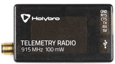
 Design with SIK Telemetry Radio in Cirkit Designer
Introduction
The SIK Telemetry Radio is a wireless communication device designed for transmitting telemetry data between a ground station and a remote vehicle. Manufactured by SIK, this module is widely used in drone and robotics applications to enable real-time data monitoring and control. It operates on open-source firmware, making it highly customizable and versatile for various telemetry needs.
Explore Projects Built with SIK Telemetry Radio
 Open Project in Cirkit Designer
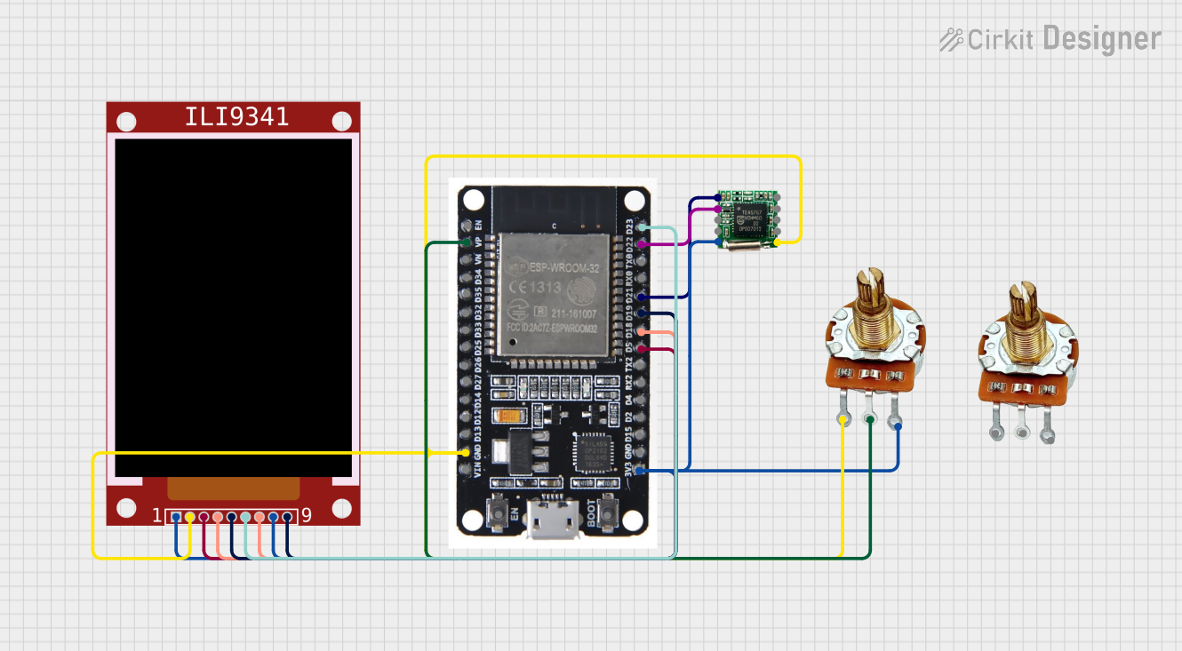 Open Project in Cirkit Designer
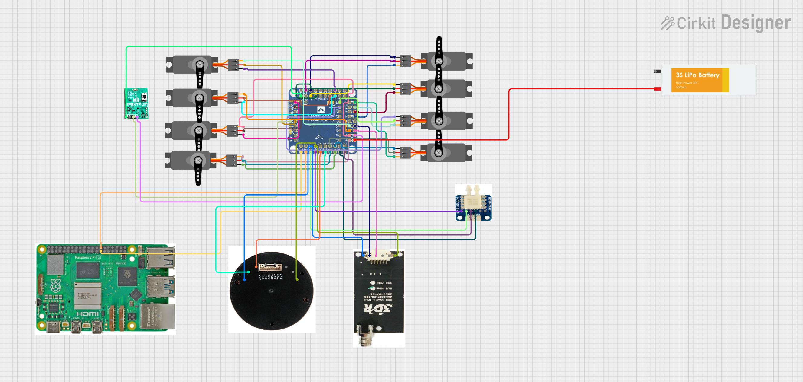 Open Project in Cirkit Designer
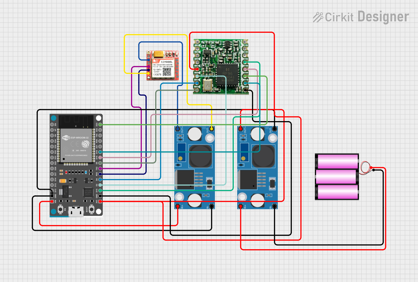 Open Project in Cirkit Designer
Explore Projects Built with SIK Telemetry Radio
Open Project in Cirkit DesignerOpen Project in Cirkit DesignerOpen Project in Cirkit DesignerOpen Project in Cirkit DesignerCommon Applications and Use Cases
- Drones and UAVs: Real-time flight data transmission between drones and ground control stations.
- Robotics: Remote monitoring and control of robotic systems.
- RC Vehicles: Telemetry data exchange for remote-controlled cars, boats, and planes.
- IoT Systems: Wireless data communication in Internet of Things (IoT) projects.
- Research and Development: Prototyping and testing wireless communication systems.
Technical Specifications
The SIK Telemetry Radio is available in multiple configurations, typically consisting of an air module (attached to the vehicle) and a ground module (connected to the ground station). Below are the key technical details:
General Specifications
| Parameter | Value |
|---|---|
| Frequency Range | 433 MHz / 915 MHz (region-dependent) |
| Modulation | Frequency Hopping Spread Spectrum (FHSS) |
| Transmission Power | Up to 100 mW (adjustable) |
| Communication Protocol | MAVLink (default) |
| Range | Up to 1 km (line of sight) |
| Data Rate | 57600 bps (default, configurable) |
| Operating Voltage | 3.3V - 5V |
| Current Consumption | ~100 mA |
| Firmware | Open-source (SiK firmware) |
| Interface | UART (TX, RX, GND, VCC) |
Pin Configuration and Descriptions
The SIK Telemetry Radio typically uses a 4-pin JST-GH connector for communication. Below is the pinout:
| Pin Number | Pin Name | Description |
|---|---|---|
| 1 | VCC | Power supply input (3.3V - 5V) |
| 2 | GND | Ground |
| 3 | TX | Transmit data (connect to RX of host) |
| 4 | RX | Receive data (connect to TX of host) |
Usage Instructions
How to Use the SIK Telemetry Radio in a Circuit
Hardware Setup:
- Connect the ground module to your computer via USB.
- Connect the air module to your vehicle or device using the 4-pin JST-GH connector.
- Ensure proper wiring:
- VCC to power supply (3.3V or 5V).
- GND to ground.
- TX to the RX pin of the host microcontroller.
- RX to the TX pin of the host microcontroller.
Software Configuration:
- Install a ground control station software like Mission Planner or QGroundControl.
- Connect the ground module to the software via the appropriate COM port.
- Ensure both modules are paired and operating on the same frequency and data rate.
Testing:
- Power on both modules and verify the connection using the ground control software.
- Check for telemetry data being transmitted and received in real time.
Important Considerations and Best Practices
- Antenna Placement: Ensure the antennas of both modules are securely connected and positioned for optimal signal strength.
- Line of Sight: For maximum range, maintain a clear line of sight between the ground and air modules.
- Power Supply: Use a stable power source to avoid communication interruptions.
- Firmware Updates: Regularly update the SiK firmware to benefit from performance improvements and bug fixes.
- Interference: Avoid operating near sources of RF interference, such as Wi-Fi routers or other high-power transmitters.
Example: Connecting to an Arduino UNO
The SIK Telemetry Radio can be connected to an Arduino UNO for telemetry data transmission. Below is an example setup:
Wiring
| SIK Telemetry Radio Pin | Arduino UNO Pin |
|---|---|
| VCC | 5V |
| GND | GND |
| TX | RX (Pin 0) |
| RX | TX (Pin 1) |
Sample Code
#include <SoftwareSerial.h>

// Define RX and TX pins for SoftwareSerial
SoftwareSerial telemetrySerial(10, 11); // RX on pin 10, TX on pin 11

void setup() {
  // Initialize hardware serial for debugging
  Serial.begin(9600);
  // Initialize telemetry serial communication
  telemetrySerial.begin(57600); // Default baud rate for SIK Telemetry Radio
  Serial.println("SIK Telemetry Radio Initialized");
}

void loop() {
  // Check if data is available from the telemetry radio
  if (telemetrySerial.available()) {
    // Read data from the telemetry radio
    String data = telemetrySerial.readString();
    // Print received data to the Serial Monitor
    Serial.println("Received: " + data);
  }

  // Example: Send data to the telemetry radio
  telemetrySerial.println("Hello from Arduino!");
  delay(1000); // Wait 1 second before sending the next message
}
Troubleshooting and FAQs
Common Issues and Solutions
No Data Transmission:
- Cause: Incorrect wiring or mismatched baud rates.
- Solution: Double-check the wiring and ensure both modules are configured with the same baud rate.
Short Range or Signal Loss:
- Cause: Poor antenna placement or interference.
- Solution: Reposition the antennas and ensure a clear line of sight. Avoid RF interference.
Modules Not Pairing:
- Cause: Different firmware versions or frequency settings.
- Solution: Update both modules to the latest SiK firmware and ensure they are configured to the same frequency.
High Latency:
- Cause: Overloaded communication channel or low data rate.
- Solution: Increase the data rate or reduce the amount of transmitted data.
FAQs
Q: Can I use the SIK Telemetry Radio with other communication protocols?
A: While the default protocol is MAVLink, the open-source firmware allows customization for other protocols.
Q: What is the maximum range of the SIK Telemetry Radio?
A: The range is up to 1 km in ideal conditions with a clear line of sight.
Q: How do I update the firmware?
A: Use the Mission Planner software to upload the latest SiK firmware to both modules.
Q: Can I use the SIK Telemetry Radio with a Raspberry Pi?
A: Yes, connect the module to the Raspberry Pi's UART pins and configure the serial communication accordingly.