Cirkit Designer LogoCirkit DesignerYour all-in-one circuit design IDE Launch Cirkit Designer App

How to Use Dissolved O2: Examples, Pinouts, and Specs

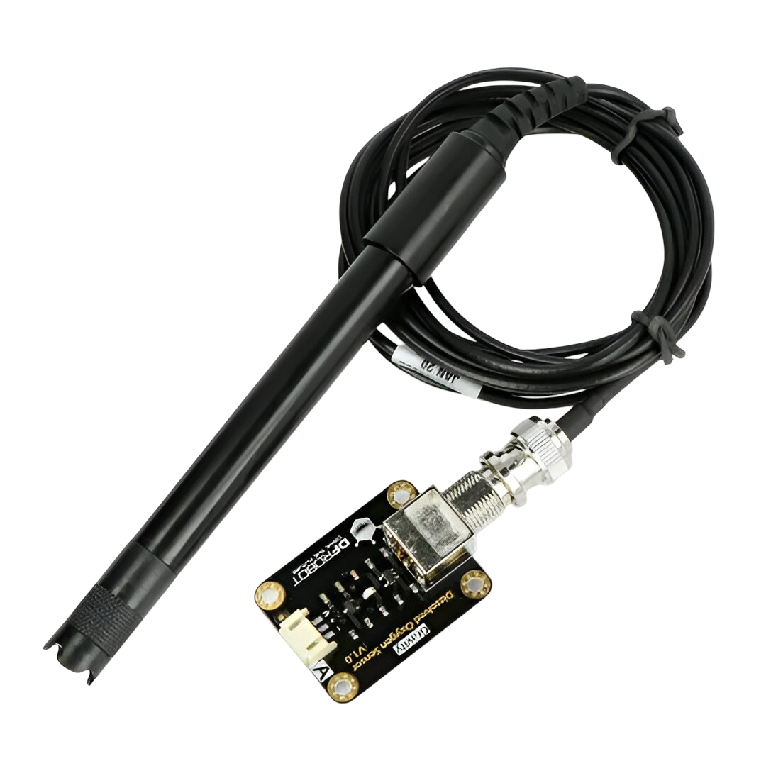
Image of Dissolved O2Design with Dissolved O2 in Cirkit Designer

Introduction

Explore Projects Built with Dissolved O2

Use Cirkit Designer to design, explore, and prototype these projects online. Some projects support real-time simulation. Click "Open Project" to start designing instantly!
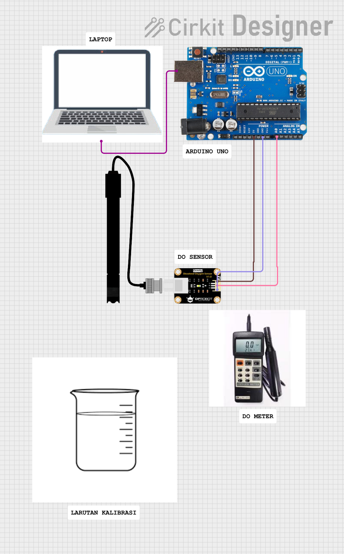
Image of Arduino-Based Dissolved Oxygen Sensor with Laptop Interface: A project utilizing Dissolved O2 in a practical application

Arduino-Based Dissolved Oxygen Sensor with Laptop Interface

This circuit involves an Arduino Uno R3 connected to a laptop via USB for power and communication. A dissolved oxygen (DO) sensor is interfaced with the Arduino, with its output connected to the A0 analog input pin, and powered by the 5V and GND pins of the Arduino. The setup is likely intended for measuring and logging dissolved oxygen levels in a solution.

Open Project in Cirkit Designer
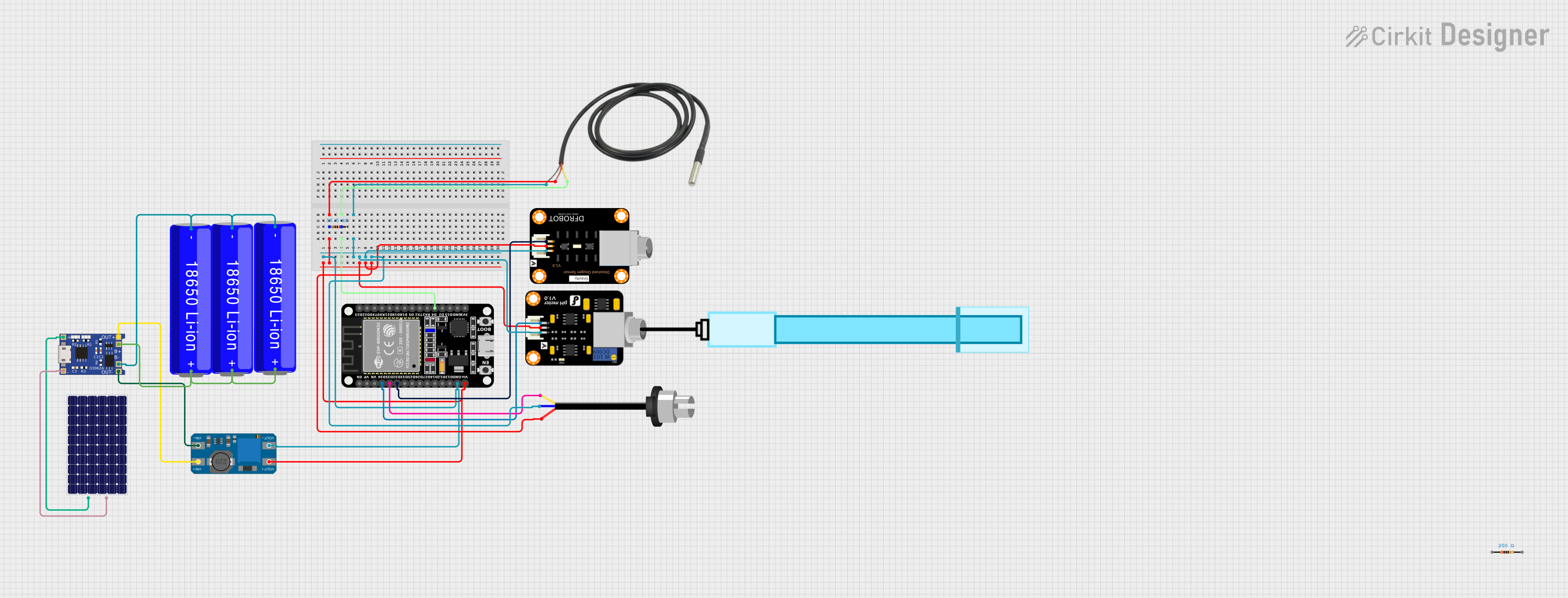
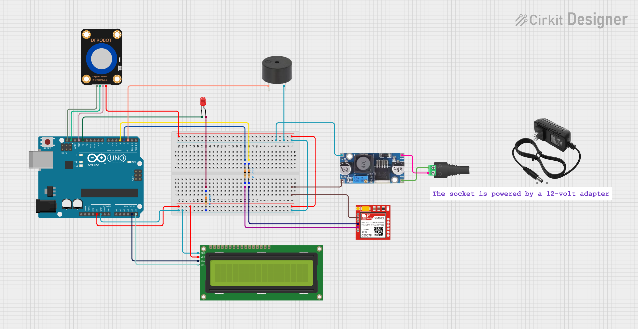
Image of ESP32-Based Water Quality Monitoring System with Solar Charging: A project utilizing Dissolved O2 in a practical application
ESP32-Based Water Quality Monitoring System with Solar Charging

This circuit features an ESP32 microcontroller interfaced with various sensors including a temperature sensor, a pH meter, a dissolved oxygen sensor, and a turbidity sensor for environmental monitoring. Power management is handled by a TP4056 charging module connected to a solar panel and three 18650 Li-ion batteries in parallel, with a MT3608 boost converter to step up the voltage for the ESP32 and sensors. The ESP32 reads sensor data and likely transmits it for analysis or remote monitoring, although the specific functionality would be determined by the microcontroller's code, which is not provided.

Open Project in Cirkit Designer
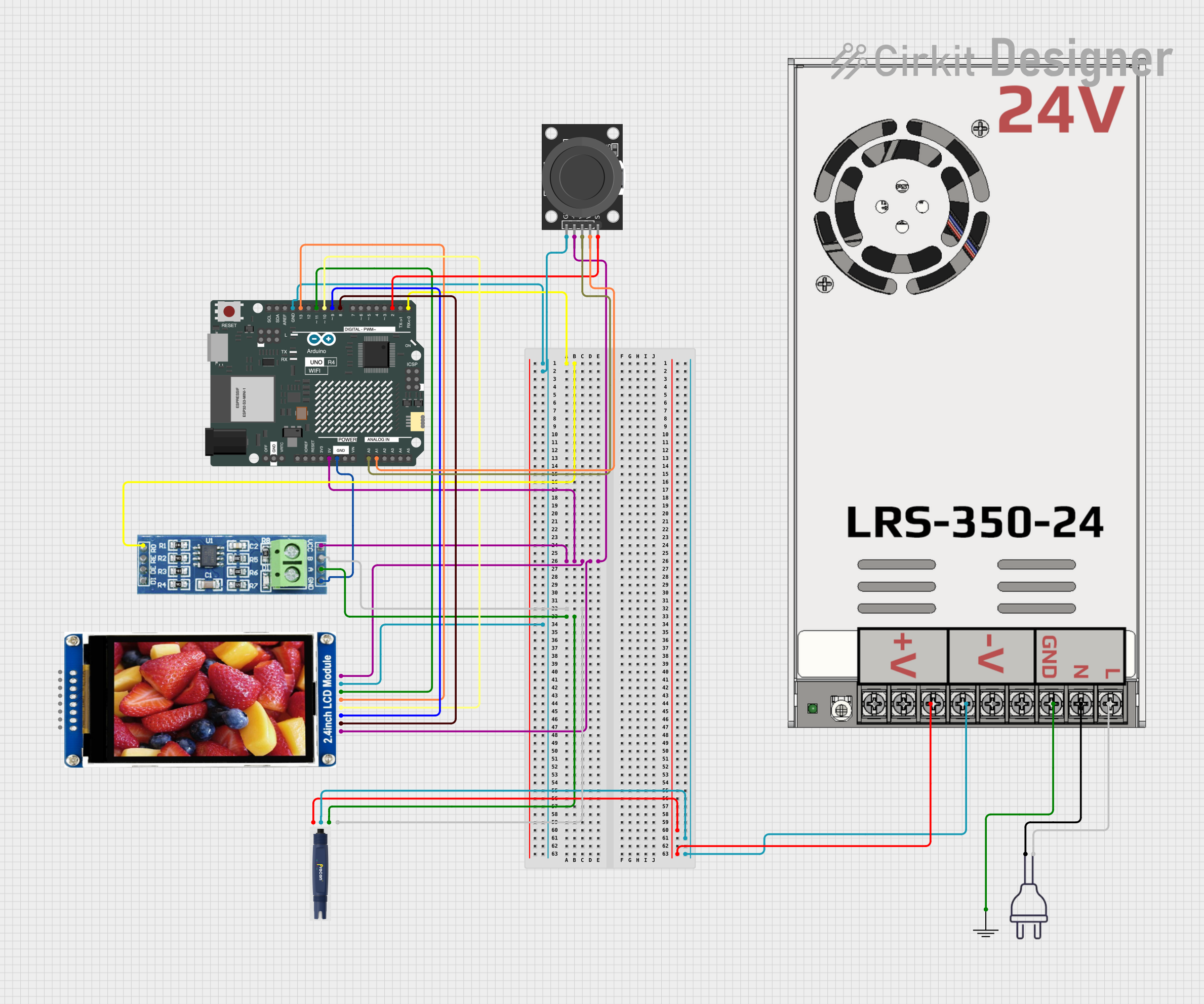
Image of Arduino UNO R4 WiFi Controlled Dissolved Ozone Monitoring System with RS485 and LCD Display: A project utilizing Dissolved O2 in a practical application
Arduino UNO R4 WiFi Controlled Dissolved Ozone Monitoring System with RS485 and LCD Display

This circuit features an Arduino UNO R4 WiFi microcontroller connected to an RS485 module for serial communication with a dissolved ozone sensor, whose readings are displayed on a 2.4" LCD. A joystick provides user input, and a power supply module converts 220V AC to 24V DC for the sensor. The Arduino's embedded code orchestrates the sensor data acquisition, display updates, and user interaction.

Open Project in Cirkit Designer

Technical Specifications

Pin Configuration and Descriptions

Analog Output Model

Pin Name Description
VCC Power supply input (5V DC)
GND Ground
AOUT Analog output signal (0–3.3V)

Digital Output Model (I2C)

Pin Name Description
VCC Power supply input (5V DC)
GND Ground
SDA I2C data line
SCL I2C clock line

Usage Instructions

How to Use the Dissolved O2 Sensor in a Circuit

  1. Power the Sensor: Connect the VCC pin to a 5V DC power source and the GND pin to ground.
  2. Connect the Output:
    • For analog models, connect the AOUT pin to an analog input pin on your microcontroller.
    • For digital models, connect the SDA and SCL pins to the corresponding I2C pins on your microcontroller.
  3. Calibrate the Sensor:
    • Immerse the sensor in air-saturated water and adjust the calibration potentiometer (if available) or use the provided calibration software.
    • For zero-point calibration, immerse the sensor in a zero-oxygen solution (e.g., sodium sulfite solution).
  4. Read the Output:
    • For analog models, read the voltage from the AOUT pin and convert it to DO concentration using the sensor's datasheet formula.
    • For digital models, use the appropriate communication protocol (e.g., I2C) to retrieve the DO value.

Important Considerations and Best Practices

Example Code for Arduino UNO (Analog Model)

// Example code to read dissolved oxygen (DO) sensor output using Arduino UNO
// and convert the analog voltage to DO concentration in ppm.

const int DO_PIN = A0; // Analog pin connected to the sensor's AOUT pin
float voltage;         // Variable to store the sensor's output voltage
float do_concentration; // Variable to store the calculated DO concentration

void setup() {
  Serial.begin(9600); // Initialize serial communication
  pinMode(DO_PIN, INPUT); // Set the DO_PIN as input
}

void loop() {
  // Read the analog voltage from the sensor
  voltage = analogRead(DO_PIN) * (5.0 / 1023.0); 
  // Convert the voltage to DO concentration (ppm)
  // Example formula: DO (ppm) = (voltage / 3.3) * 20
  do_concentration = (voltage / 3.3) * 20;

  // Print the results to the Serial Monitor
  Serial.print("Voltage: ");
  Serial.print(voltage);
  Serial.print(" V, DO Concentration: ");
  Serial.print(do_concentration);
  Serial.println(" ppm");

  delay(1000); // Wait for 1 second before the next reading
}

Troubleshooting and FAQs

Common Issues and Solutions

  1. No Output Signal:

    • Ensure the sensor is properly powered (check VCC and GND connections).
    • Verify that the output pin is correctly connected to the microcontroller.
  2. Inaccurate Readings:

    • Check if the sensor is calibrated correctly.
    • Clean the sensor membrane to remove any fouling or debris.
    • Ensure proper temperature compensation is applied.
  3. Fluctuating Readings:

    • Avoid air bubbles on the sensor membrane.
    • Ensure stable water flow around the sensor during measurement.
  4. Sensor Not Responding to Calibration:

    • Verify the calibration solution's accuracy.
    • Check for damage to the sensor membrane or internal components.

FAQs

Q: Can the sensor be used in saltwater?
A: Yes, but ensure the sensor is rated for use in saline environments. Calibration may need adjustment for salinity.

Q: How often should the sensor be calibrated?
A: Calibration frequency depends on usage. For critical applications, calibrate weekly or before each use.

Q: Can the sensor measure DO in high-temperature liquids?
A: Most sensors operate up to 50°C. Check the sensor's datasheet for specific temperature limits.

Q: What is the lifespan of the sensor?
A: The lifespan varies but is typically 1–2 years with proper maintenance. Replace the membrane or electrolyte as needed.