
How to Use Directional Sw: Examples, Pinouts, and Specs
 Design with Directional Sw in Cirkit Designer
Introduction
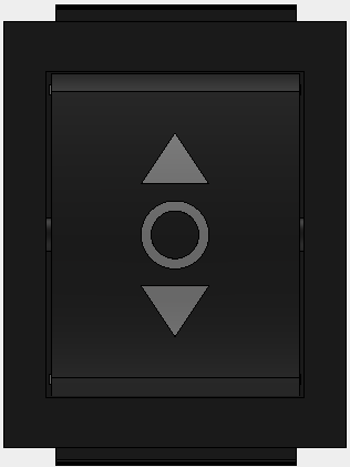
A directional switch is an electronic component designed to control the flow of electrical signals in a specific direction. It is commonly used in communication systems, audio equipment, and other signal-routing applications where precise control of signal direction is required. By enabling or disabling specific signal paths, directional switches ensure efficient signal management and prevent interference between different circuits.
Explore Projects Built with Directional Sw
 Open Project in Cirkit Designer
 Open Project in Cirkit Designer
 Open Project in Cirkit Designer
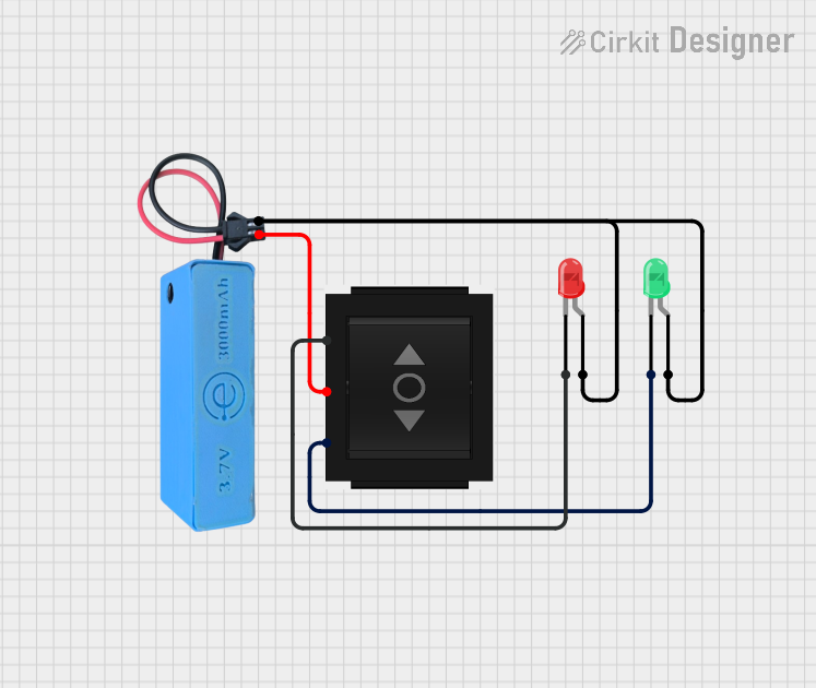 Open Project in Cirkit Designer
Explore Projects Built with Directional Sw
Open Project in Cirkit DesignerOpen Project in Cirkit DesignerOpen Project in Cirkit DesignerOpen Project in Cirkit DesignerCommon Applications and Use Cases
- Communication Systems: Routing signals between transmitters and receivers.
- Audio Equipment: Switching between audio input/output sources.
- Test and Measurement Devices: Directing signals to specific measurement instruments.
- RF Systems: Controlling the flow of radio frequency signals in antennas or filters.
Technical Specifications
Below are the general technical specifications for a typical directional switch. Note that specific models may vary, so always refer to the manufacturer's datasheet for exact details.
Key Technical Details
- Operating Voltage: 3.3V to 12V (depending on the model)
- Current Rating: Up to 1A
- Frequency Range: DC to 3 GHz (for RF directional switches)
- Impedance: 50Ω (typical for RF applications)
- Switching Time: <10 ms
- Control Type: Mechanical or electronic (e.g., relay-based or solid-state)
Pin Configuration and Descriptions
The pin configuration of a directional switch depends on its type (e.g., SPDT, DPDT). Below is an example for a Single Pole Double Throw (SPDT) directional switch:
| Pin Number | Label | Description |
|---|---|---|
| 1 | COM | Common terminal where the input signal is applied. |
| 2 | NO | Normally Open terminal; connects to COM when the switch is activated. |
| 3 | NC | Normally Closed terminal; connects to COM when the switch is not activated. |
| 4 | GND | Ground connection for the switch. |
| 5 | VCC | Power supply input for electronic control (if applicable). |
| 6 | CTRL | Control signal input to toggle between NO and NC (for electronically controlled switches). |
Usage Instructions
How to Use the Component in a Circuit
- Identify the Terminals: Refer to the pin configuration table to identify the COM, NO, NC, GND, VCC, and CTRL pins.
- Connect the Power Supply: If the switch is electronically controlled, connect the VCC and GND pins to the appropriate power supply (e.g., 5V or 12V, depending on the switch specifications).
- Signal Routing: Connect the input signal to the COM pin. The output signal will be routed to either the NO or NC pin based on the control signal.
- Control Signal: For electronically controlled switches, apply a control signal (e.g., HIGH or LOW) to the CTRL pin to toggle the switch state.
Important Considerations and Best Practices
- Voltage and Current Ratings: Ensure the input signal does not exceed the switch's voltage and current ratings to avoid damage.
- Debouncing: For mechanical switches, consider adding a debouncing circuit to eliminate signal noise caused by contact bounce.
- Impedance Matching: In RF applications, ensure proper impedance matching (e.g., 50Ω) to minimize signal loss.
- Isolation: Verify the isolation between the NO and NC terminals to prevent signal leakage.
Example: Using a Directional Switch with Arduino UNO
Below is an example of controlling an electronically controlled directional switch using an Arduino UNO:
// Define the control pin connected to the directional switch
const int controlPin = 7;

void setup() {
  // Set the control pin as an output
  pinMode(controlPin, OUTPUT);
}

void loop() {
  // Activate the switch (connect COM to NO)
  digitalWrite(controlPin, HIGH);
  delay(1000); // Keep the switch active for 1 second

  // Deactivate the switch (connect COM to NC)
  digitalWrite(controlPin, LOW);
  delay(1000); // Keep the switch inactive for 1 second
}
Note: Ensure the control signal voltage matches the switch's CTRL pin requirements.
Troubleshooting and FAQs
Common Issues and Solutions
Switch Not Responding to Control Signal
- Cause: Incorrect voltage level on the CTRL pin.
- Solution: Verify the control signal voltage matches the switch's specifications.
Signal Loss or Distortion
- Cause: Impedance mismatch or poor connections.
- Solution: Check all connections and ensure proper impedance matching.
Switch Overheating
- Cause: Exceeding the current or voltage rating.
- Solution: Ensure the input signal is within the specified ratings.
Mechanical Switch Fails to Toggle
- Cause: Worn-out contacts or debris inside the switch.
- Solution: Clean the switch contacts or replace the switch if necessary.
FAQs
Q: Can I use a directional switch for AC signals?
- A: Yes, but ensure the switch is rated for AC operation and the voltage/current ratings are not exceeded.
Q: What is the difference between a mechanical and an electronic directional switch?
- A: Mechanical switches use physical contacts to toggle signal paths, while electronic switches use solid-state components (e.g., transistors or relays) for faster and more reliable operation.
Q: How do I test a directional switch?
- A: Use a multimeter to check continuity between the COM and NO/NC terminals while toggling the switch state.
By following this documentation, you can effectively integrate and troubleshoot a directional switch in your electronic projects.