How to Use Nema 17: Examples, Pinouts, and Specs
Introduction
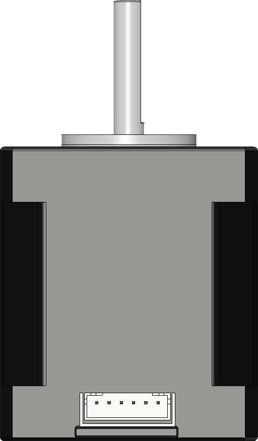
The Nema 17 stepper motor, specifically the Motech Motor MT-1704HS168A, is a highly reliable and precise motor commonly used in applications requiring accurate control of movement and positioning. With a 1.7 x 1.7 inch faceplate, this stepper motor is a popular choice for 3D printers, CNC machines, and other automated equipment.
Explore Projects Built with Nema 17
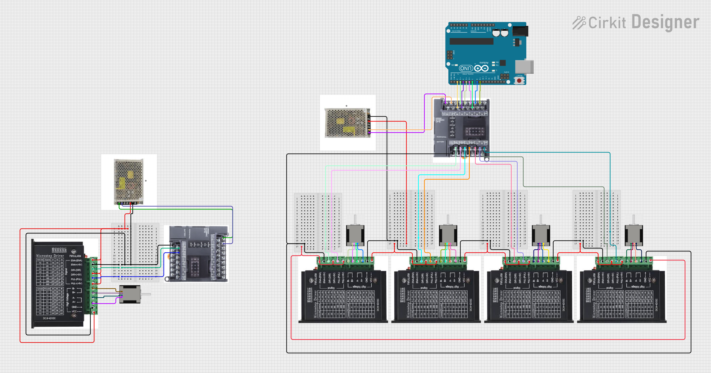

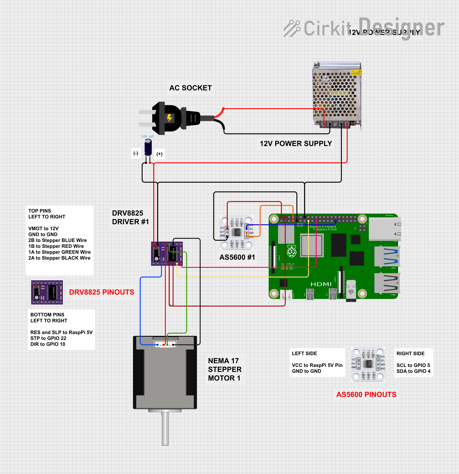
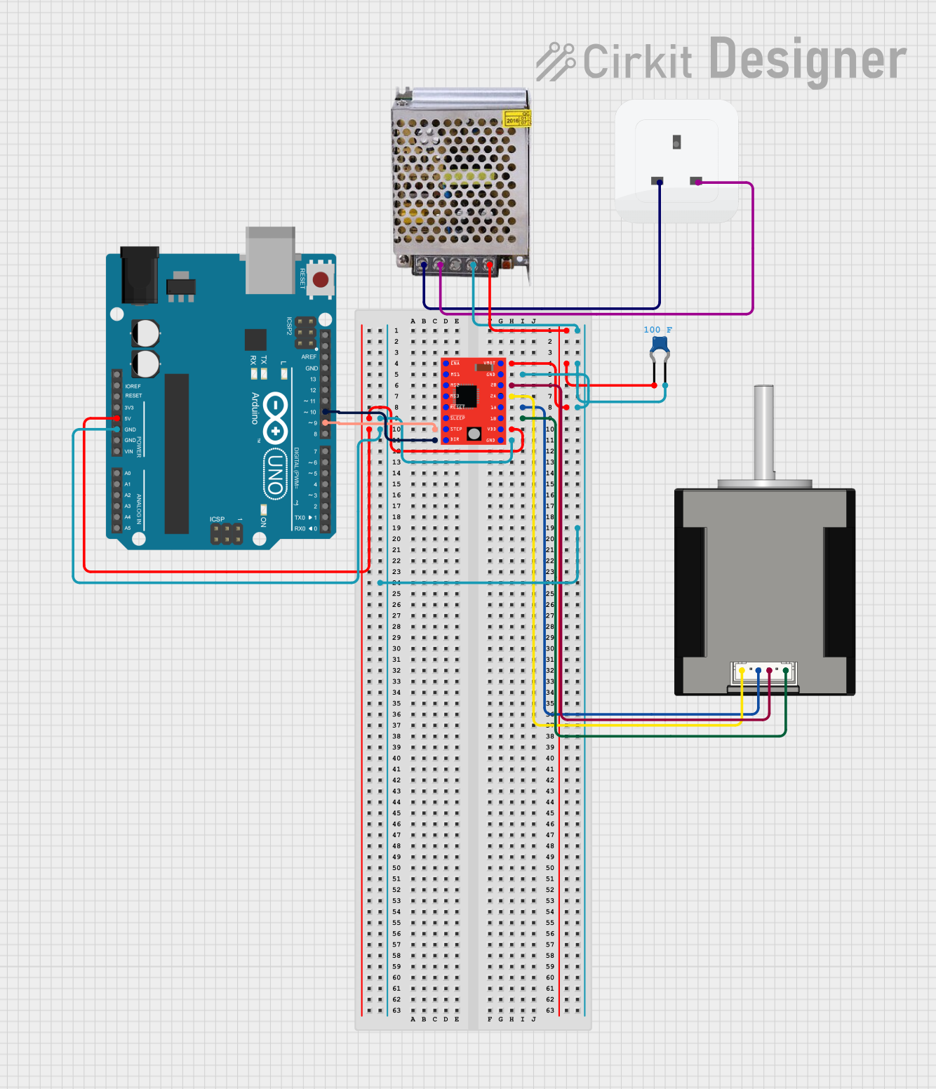
Explore Projects Built with Nema 17
Technical Specifications
Key Technical Details
| Parameter | Value |
|---|---|
| Manufacturer | Motech Motor |
| Part ID | MT-1704HS168A |
| Step Angle | 1.8° |
| Holding Torque | 4.2 kg-cm |
| Rated Current | 1.68 A/phase |
| Voltage | 2.8 V |
| Resistance | 1.65 Ω/phase |
| Inductance | 3.2 mH/phase |
| Number of Leads | 4 |
| Shaft Diameter | 5 mm |
| Motor Length | 40 mm |
| Weight | 280 g |
Pin Configuration and Descriptions
The Nema 17 stepper motor has four leads, which are typically color-coded. The table below describes the pin configuration:
| Lead Color | Function | Description |
|---|---|---|
| Red | A+ | Phase A positive |
| Blue | A- | Phase A negative |
| Green | B+ | Phase B positive |
| Black | B- | Phase B negative |
Usage Instructions
How to Use the Component in a Circuit
To use the Nema 17 stepper motor in a circuit, you will need a stepper motor driver, such as the A4988 or DRV8825, and a microcontroller, such as an Arduino UNO. Below is a basic setup guide:
Connect the Motor to the Driver:
- Connect the Red lead to the A+ terminal of the driver.
- Connect the Blue lead to the A- terminal of the driver.
- Connect the Green lead to the B+ terminal of the driver.
- Connect the Black lead to the B- terminal of the driver.
Connect the Driver to the Arduino:
- Connect the STEP pin of the driver to a digital pin on the Arduino (e.g., pin 2).
- Connect the DIR pin of the driver to another digital pin on the Arduino (e.g., pin 3).
- Connect the EN (Enable) pin of the driver to a digital pin on the Arduino (e.g., pin 4) or ground it if not used.
- Connect the VDD and GND pins of the driver to the 5V and GND pins of the Arduino, respectively.
- Connect the VMOT and GND pins of the driver to an external power supply (e.g., 12V).
Arduino Code Example:
// Define stepper motor connections and steps per revolution
#define dirPin 3
#define stepPin 2
#define motorSteps 200

void setup() {
  // Set the pins as outputs
  pinMode(stepPin, OUTPUT);
  pinMode(dirPin, OUTPUT);
}

void loop() {
  // Set the direction clockwise
  digitalWrite(dirPin, HIGH);

  // Move the motor 200 steps (one revolution)
  for(int x = 0; x < motorSteps; x++) {
    digitalWrite(stepPin, HIGH);
    delayMicroseconds(1000); // Adjust delay for speed control
    digitalWrite(stepPin, LOW);
    delayMicroseconds(1000);
  }

  delay(1000); // Wait for a second

  // Set the direction counterclockwise
  digitalWrite(dirPin, LOW);

  // Move the motor 200 steps (one revolution)
  for(int x = 0; x < motorSteps; x++) {
    digitalWrite(stepPin, HIGH);
    delayMicroseconds(1000);
    digitalWrite(stepPin, LOW);
    delayMicroseconds(1000);
  }

  delay(1000); // Wait for a second
}
Important Considerations and Best Practices
- Current Limiting: Ensure that the current limit on the stepper driver is set correctly to prevent overheating and damage to the motor.
- Power Supply: Use an appropriate power supply that matches the voltage and current requirements of the motor.
- Cooling: Provide adequate cooling for the stepper driver and motor if they are used in high-load applications.
- Microstepping: Utilize microstepping settings on the driver for smoother and quieter motor operation.
Troubleshooting and FAQs
Common Issues Users Might Face
Motor Not Moving:
- Solution: Check all connections and ensure the driver is receiving power. Verify that the Arduino code is correctly uploaded and running.
Motor Vibrates but Doesn't Rotate:
- Solution: Ensure the correct wiring of the motor leads to the driver. Double-check the step and direction signals from the Arduino.
Overheating:
- Solution: Verify that the current limit on the driver is set correctly. Ensure proper ventilation and cooling for the motor and driver.
Inconsistent Movement:
- Solution: Check for loose connections and ensure the power supply is stable. Verify the microstepping settings on the driver.
Solutions and Tips for Troubleshooting
- Double-Check Wiring: Ensure all connections are secure and correctly matched to the driver and motor.
- Use a Multimeter: Measure the voltage and current at various points in the circuit to identify any discrepancies.
- Consult Datasheets: Refer to the datasheets of the motor and driver for detailed specifications and troubleshooting tips.
- Test with Simple Code: Use basic test code to isolate issues and verify the functionality of the motor and driver.
By following this documentation, users can effectively integrate the Nema 17 stepper motor into their projects, ensuring precise and reliable performance.