How to Use esp: Examples, Pinouts, and Specs
Introduction
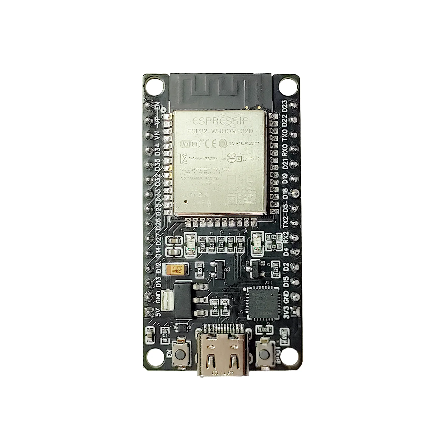
The ESP32, manufactured by Mbutronics, is a powerful and versatile system-on-chip (SoC) microcontroller designed for IoT (Internet of Things) applications. It combines low power consumption with integrated Wi-Fi and Bluetooth capabilities, making it an ideal choice for a wide range of wireless communication projects. The ESP32 is widely used in smart home devices, wearable electronics, industrial automation, and other IoT applications due to its robust performance and cost-effectiveness.
Explore Projects Built with esp
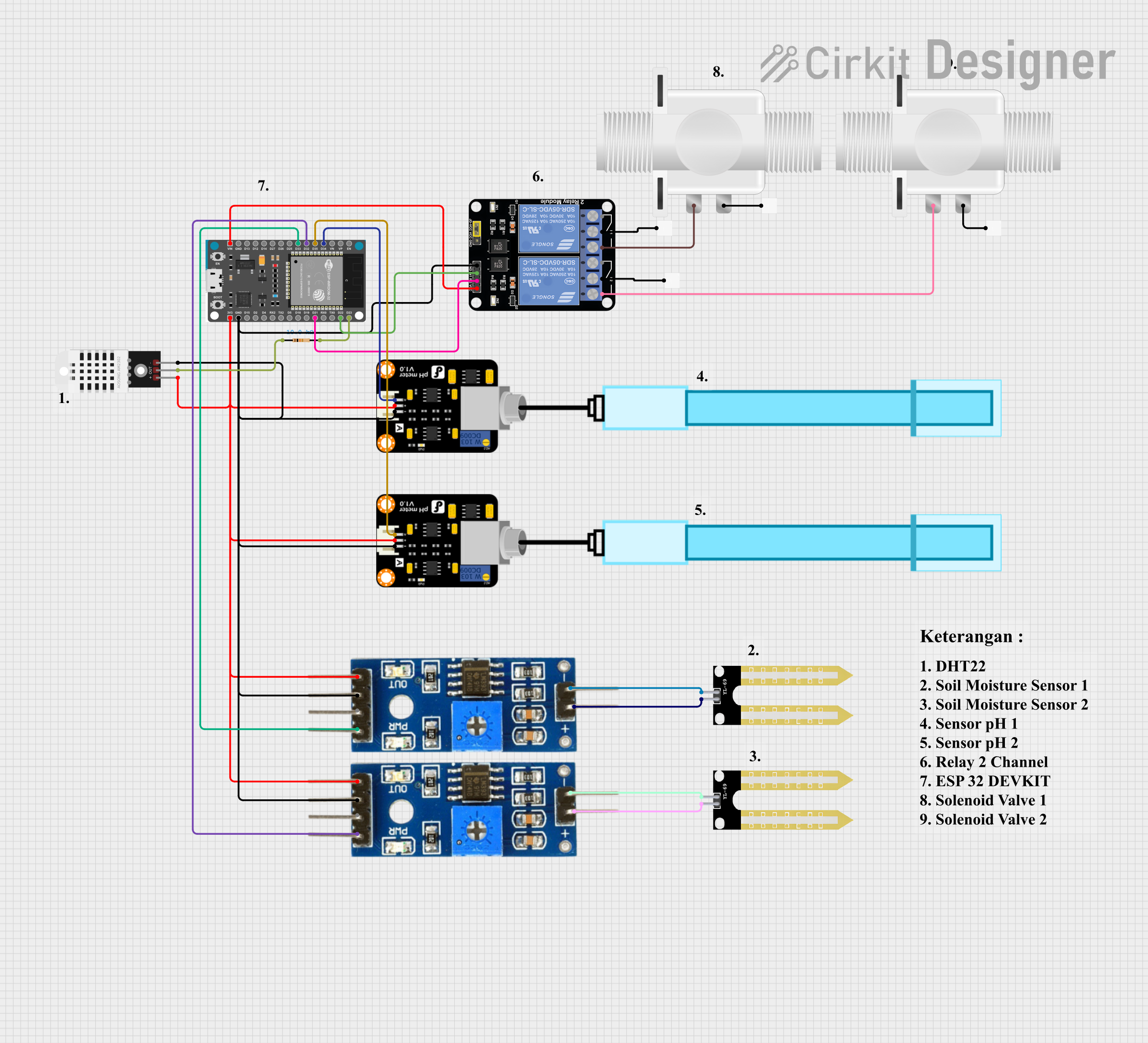

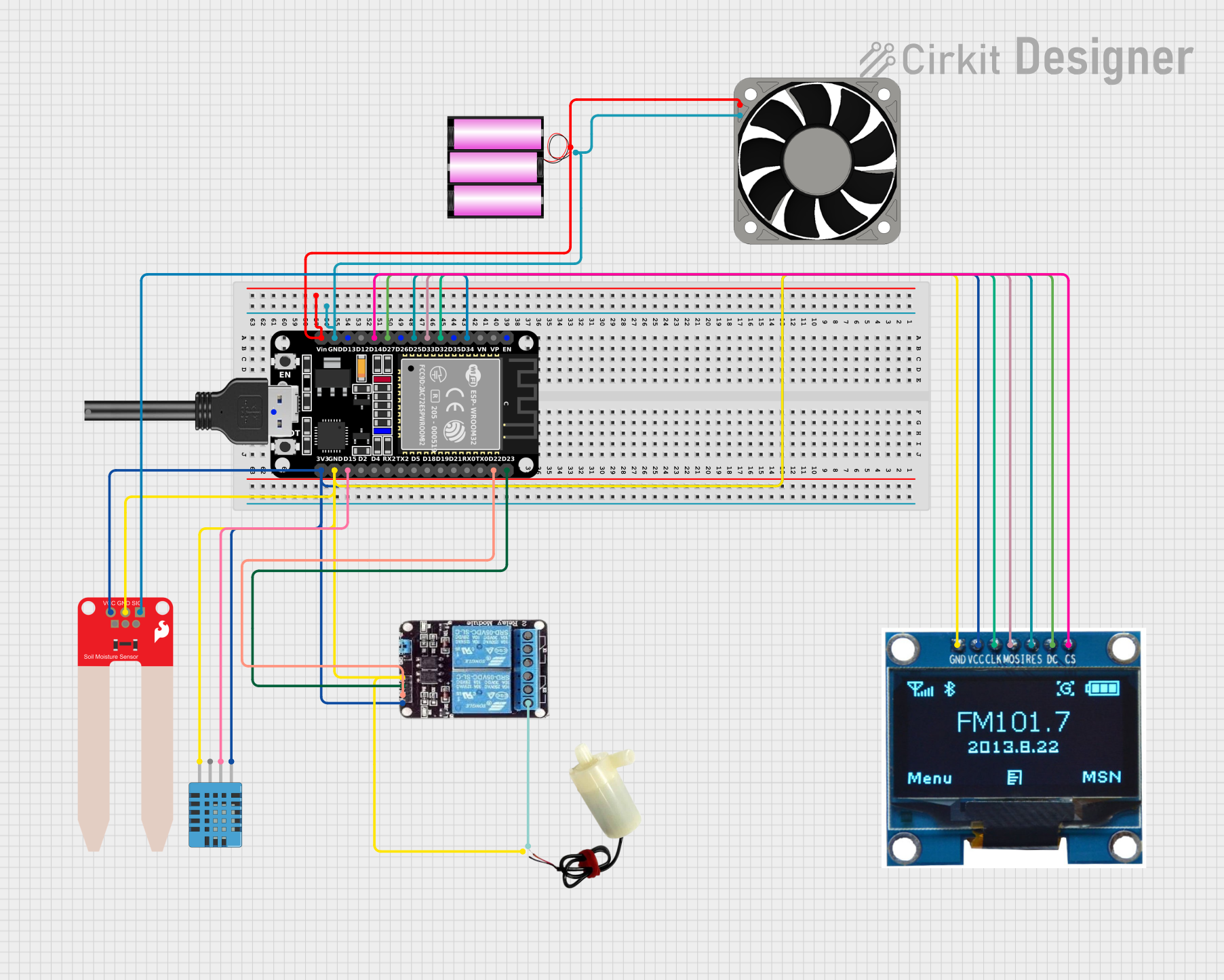
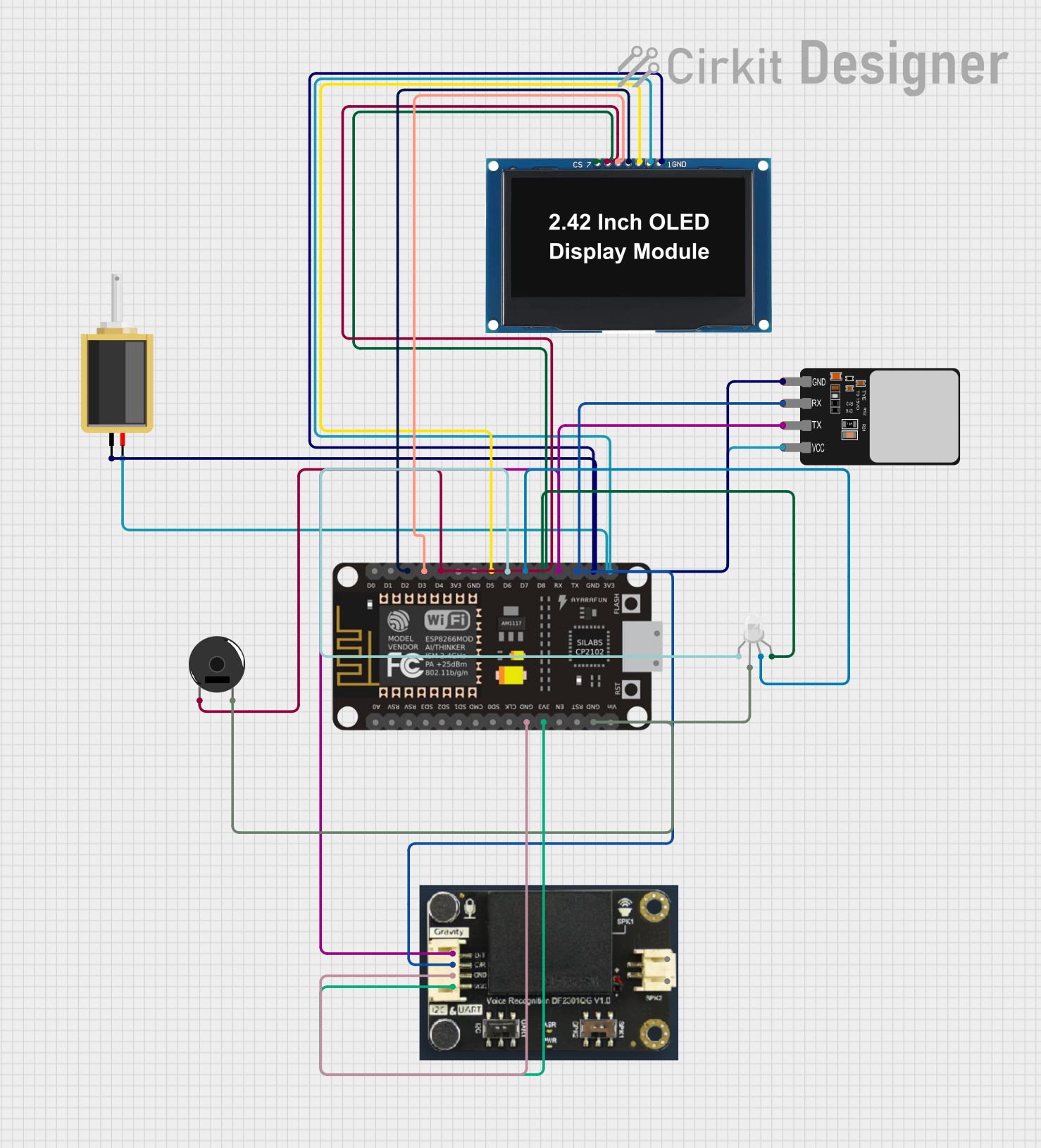
Explore Projects Built with esp
Common Applications and Use Cases
- Smart Home Automation: Control and monitor devices such as lights, thermostats, and security systems.
- Wearable Devices: Build fitness trackers, smartwatches, and health monitoring systems.
- Industrial IoT: Enable wireless communication in industrial sensors and actuators.
- Robotics: Use as a controller for robots with wireless connectivity.
- Prototyping and Development: Ideal for hobbyists and engineers creating IoT prototypes.
Technical Specifications
The ESP32 is packed with features that make it suitable for a variety of applications. Below are its key technical specifications:
Key Technical Details
- Manufacturer: Mbutronics
- Part ID: ESP32
- Processor: Dual-core Xtensa® 32-bit LX6 microprocessor
- Clock Speed: Up to 240 MHz
- RAM: 520 KB SRAM
- Flash Memory: 4 MB (varies by model)
- Wi-Fi: 802.11 b/g/n
- Bluetooth: v4.2 BR/EDR and BLE
- Operating Voltage: 3.3V
- GPIO Pins: 34 (multipurpose)
- ADC Channels: 18 (12-bit resolution)
- DAC Channels: 2
- PWM Outputs: 16
- Communication Protocols: UART, SPI, I2C, I2S, CAN, Ethernet
- Power Consumption: Ultra-low power in deep sleep mode (~10 µA)
- Operating Temperature: -40°C to +125°C
Pin Configuration and Descriptions
The ESP32 has a rich set of GPIO pins that can be configured for various functions. Below is a table summarizing the key pins:
| Pin Name | Function | Description |
|---|---|---|
| GPIO0 | Input/Output, Boot Mode | Used for boot mode selection during startup. |
| GPIO2 | Input/Output, ADC, PWM | General-purpose pin with ADC and PWM capabilities. |
| GPIO12 | Input/Output, ADC, Touch | Can be used as a touch sensor or ADC input. |
| GPIO13 | Input/Output, ADC, PWM | General-purpose pin with ADC and PWM capabilities. |
| GPIO15 | Input/Output, ADC, PWM | General-purpose pin with ADC and PWM capabilities. |
| EN | Enable | Active high pin to enable the chip. |
| 3V3 | Power | Provides 3.3V power output. |
| GND | Ground | Ground connection. |
| TX0 | UART Transmit | UART0 transmit pin for serial communication. |
| RX0 | UART Receive | UART0 receive pin for serial communication. |
Note: Some GPIO pins have specific restrictions or functions during boot. Refer to the datasheet for detailed pin behavior.
Usage Instructions
The ESP32 can be used in a variety of circuits and projects. Below are the steps to get started:
How to Use the ESP32 in a Circuit
- Power Supply: Provide a stable 3.3V power supply to the ESP32. Avoid exceeding the voltage limit to prevent damage.
- Programming: Use a USB-to-serial adapter or a development board with built-in USB connectivity to program the ESP32.
- Connections:
- Connect the EN pin to 3.3V to enable the chip.
- Use the TX0 and RX0 pins for serial communication with a computer or other devices.
- Connect peripherals (e.g., sensors, actuators) to the GPIO pins as needed.
- Flashing Firmware: Use the Arduino IDE or Espressif's ESP-IDF to upload code to the ESP32.
Important Considerations and Best Practices
- Voltage Levels: Ensure all connected devices operate at 3.3V logic levels. Use level shifters if interfacing with 5V devices.
- Boot Mode: Pull GPIO0 low during startup to enter bootloader mode for programming.
- Deep Sleep: Use deep sleep mode to conserve power in battery-powered applications.
- Antenna Placement: Ensure the onboard antenna has sufficient clearance from metal objects to avoid signal interference.
Example Code for Arduino UNO Integration
The following example demonstrates how to connect the ESP32 to an Arduino UNO and send data via serial communication:
// Example: Sending data from Arduino UNO to ESP32 via Serial
// Ensure the ESP32 is connected to the Arduino's TX and RX pins properly.

void setup() {
  Serial.begin(9600); // Initialize serial communication at 9600 baud
  delay(1000);        // Wait for the serial connection to stabilize
}

void loop() {
  Serial.println("Hello from Arduino!"); // Send a message to the ESP32
  delay(1000);                           // Wait 1 second before sending again
}
Note: When connecting the ESP32 to an Arduino UNO, use a voltage divider or level shifter to step down the Arduino's 5V TX signal to 3.3V.
Troubleshooting and FAQs
Common Issues and Solutions
ESP32 Not Responding to Commands:
- Cause: Incorrect boot mode.
- Solution: Ensure GPIO0 is pulled low during startup for programming mode.
Wi-Fi Connection Fails:
- Cause: Incorrect SSID or password.
- Solution: Double-check the Wi-Fi credentials in your code.
Overheating:
- Cause: Excessive current draw or poor ventilation.
- Solution: Ensure proper heat dissipation and avoid overloading the GPIO pins.
Serial Communication Issues:
- Cause: Mismatched baud rate or incorrect wiring.
- Solution: Verify the baud rate and check the TX/RX connections.
FAQs
Q: Can the ESP32 operate on 5V?
- A: No, the ESP32 operates at 3.3V. Use a voltage regulator or level shifter for 5V systems.
Q: How do I reset the ESP32?
- A: Press the reset button on the development board or toggle the EN pin.
Q: Can I use the ESP32 for Bluetooth audio streaming?
- A: Yes, the ESP32 supports Bluetooth audio streaming using the A2DP profile.
Q: What is the maximum Wi-Fi range of the ESP32?
- A: The range depends on the environment but typically extends up to 100 meters in open space.
By following this documentation, you can effectively integrate the ESP32 into your projects and troubleshoot common issues.