How to Use splicing connector 2: Examples, Pinouts, and Specs
Introduction
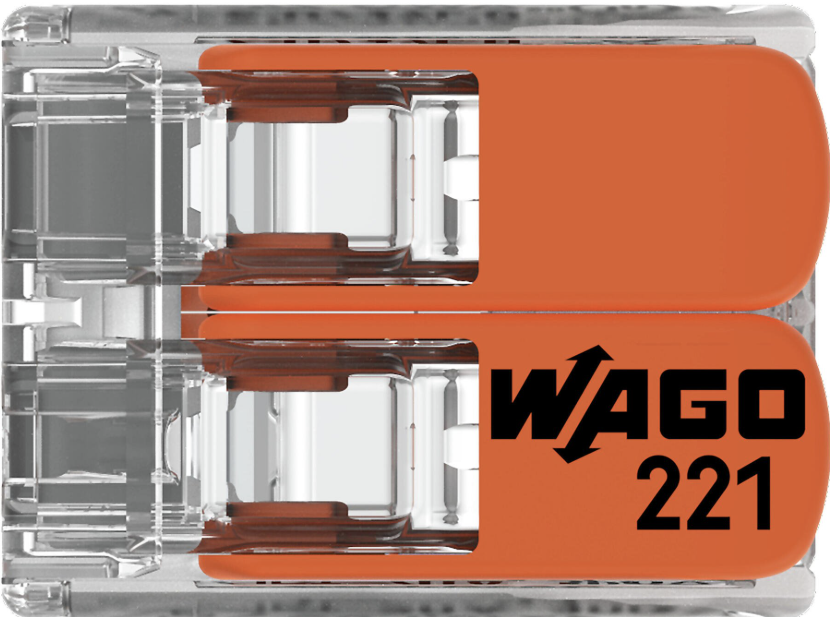
The Splicing Connector 2 by WAGO is a compact and efficient solution for joining two or more electrical wires or cables. Designed for ease of use, it ensures a secure and reliable connection for signal transmission or power distribution. This component is widely used in electrical installations, control panels, and DIY projects due to its tool-free operation and robust design.
Explore Projects Built with splicing connector 2


Explore Projects Built with splicing connector 2
Common Applications and Use Cases
- Electrical wiring in residential, commercial, and industrial installations
- Connecting wires in control panels and distribution boxes
- DIY electronics and prototyping projects
- Signal and power distribution in low-voltage systems
Technical Specifications
The following table outlines the key technical details of the Splicing Connector 2:
| Parameter | Specification |
|---|---|
| Manufacturer | WAGO |
| Part ID | Splicing Connector |
| Number of Connections | 2 |
| Wire Size Compatibility | 28–12 AWG (0.08–4 mm²) |
| Voltage Rating | 450 V |
| Current Rating | 32 A |
| Operating Temperature | -40°C to +85°C |
| Housing Material | Polycarbonate (PC), flame-retardant |
| Connection Type | Push-in spring technology |
| Dimensions (L x W x H) | 20.5 mm x 13.1 mm x 8.3 mm |
Pin Configuration and Descriptions
The Splicing Connector 2 does not have traditional pins but features two wire entry points. The table below describes the wire entry points:
| Entry Point | Description |
|---|---|
| Entry Point 1 | Insert the first wire (28–12 AWG) |
| Entry Point 2 | Insert the second wire (28–12 AWG) |
Usage Instructions
How to Use the Splicing Connector 2 in a Circuit
- Prepare the Wires: Strip approximately 10–12 mm of insulation from the ends of the wires you wish to connect.
- Insert the Wires: Push the stripped end of the first wire into Entry Point 1 and the second wire into Entry Point 2. Ensure the wires are fully inserted and securely held by the spring mechanism.
- Verify the Connection: Gently tug on the wires to confirm they are firmly secured.
- Test the Circuit: Power on the circuit and verify the connection is functioning as intended.
Important Considerations and Best Practices
- Ensure the wire size is within the specified range (28–12 AWG) for optimal performance.
- Avoid using damaged or corroded wires, as this may compromise the connection.
- Do not exceed the voltage and current ratings of the connector (450 V, 32 A).
- Use the connector in environments within the specified operating temperature range (-40°C to +85°C).
- For added safety, ensure the connector is housed in an enclosure if used in high-voltage or high-current applications.
Example: Connecting to an Arduino UNO
While the Splicing Connector 2 is not directly programmable, it can be used to connect power or signals to an Arduino UNO. For example, you can use it to connect a 5V power supply to the Arduino's VIN and GND pins.
// Example: Blinking an LED using a power connection via Splicing Connector 2
// Ensure the 5V power supply is securely connected to the Arduino using the connector

int ledPin = 13; // Pin connected to the onboard LED

void setup() {
  pinMode(ledPin, OUTPUT); // Set the LED pin as an output
}

void loop() {
  digitalWrite(ledPin, HIGH); // Turn the LED on
  delay(1000);                // Wait for 1 second
  digitalWrite(ledPin, LOW);  // Turn the LED off
  delay(1000);                // Wait for 1 second
}
Troubleshooting and FAQs
Common Issues Users Might Face
- Loose Connections: If the wires are not securely held, the connection may fail.
- Solution: Ensure the wires are fully inserted into the connector and the spring mechanism is engaged.
- Overheating: The connector may overheat if the current exceeds 32 A.
- Solution: Verify the current rating of your circuit and ensure it does not exceed the connector's specifications.
- Wire Slippage: Stripped wires may slip out of the connector.
- Solution: Strip the correct length of insulation (10–12 mm) and ensure the wire is clean and undamaged.
FAQs
Q1: Can I reuse the Splicing Connector 2?
A1: Yes, the connector is reusable. Simply remove the wires by pulling them out while pressing the release lever (if applicable).
Q2: Is the connector suitable for outdoor use?
A2: The connector is not waterproof. Use it in a weatherproof enclosure if outdoor use is required.
Q3: Can I connect wires of different sizes?
A3: Yes, as long as the wire sizes are within the specified range (28–12 AWG).
Q4: Does the connector require any special tools?
A4: No, the push-in spring technology allows for tool-free operation.