How to Use HS-S53-L: Examples, Pinouts, and Specs
Introduction
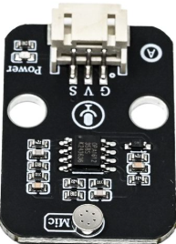
The HS-S53-L is a high-speed, low-power, surface-mount switch designed for use in a variety of electronic applications. Its compact design makes it ideal for space-constrained environments, while its reliable performance ensures efficient signal routing and control. This component is widely used in signal switching, multiplexing, and control circuits in consumer electronics, industrial systems, and communication devices.
Explore Projects Built with HS-S53-L
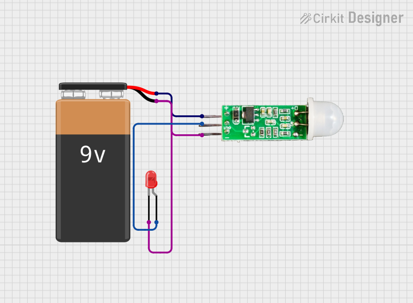

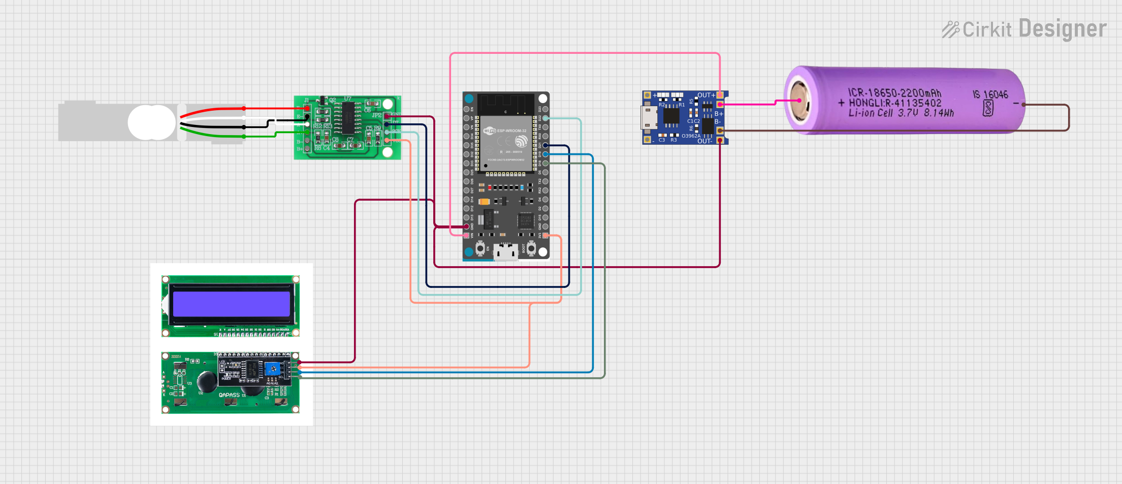
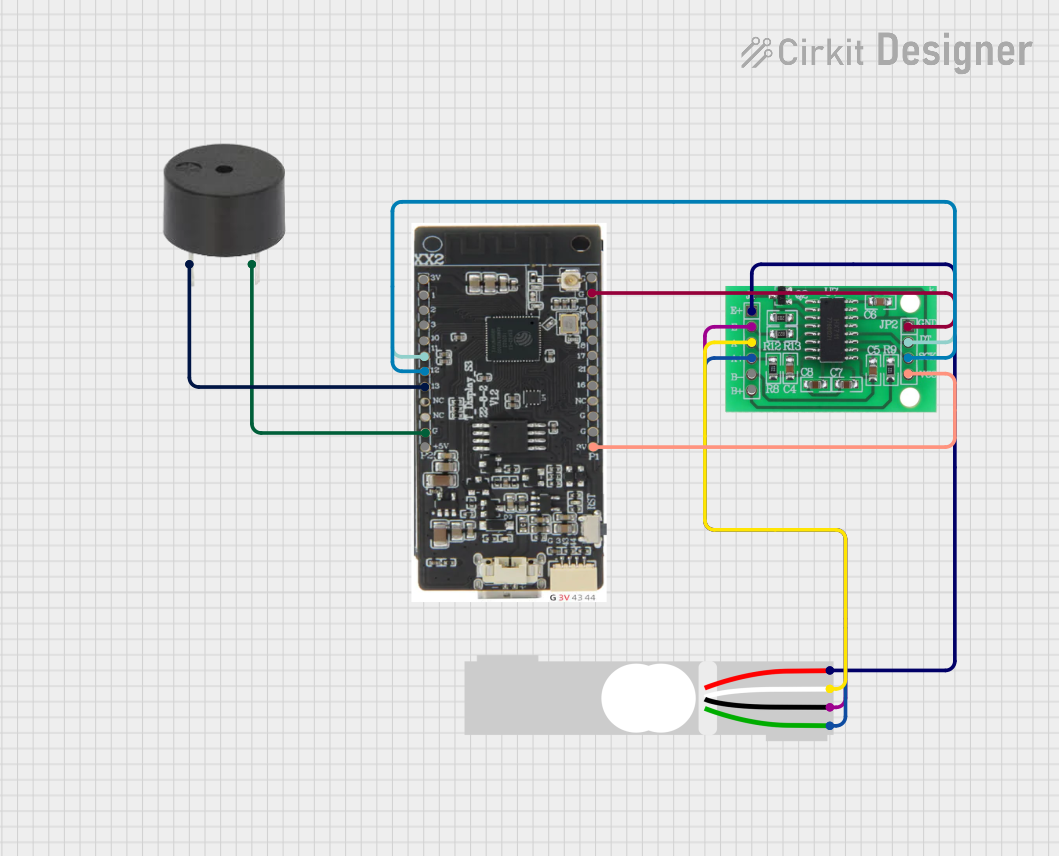
Explore Projects Built with HS-S53-L
Common Applications
- Signal routing in communication systems
- Multiplexing in data acquisition systems
- Control circuits in industrial automation
- Consumer electronics requiring compact and efficient switching
Technical Specifications
Key Technical Details
| Parameter | Value |
|---|---|
| Operating Voltage | 2.7V to 5.5V |
| Maximum Switching Speed | 50 MHz |
| On-Resistance (RON) | 5 Ω (typical) |
| Power Consumption | 0.1 mW (typical) |
| Package Type | Surface-Mount (SOT-23-6) |
| Operating Temperature | -40°C to +85°C |
Pin Configuration and Descriptions
The HS-S53-L is housed in a 6-pin SOT-23 package. The pinout and descriptions are as follows:
| Pin Number | Pin Name | Description |
|---|---|---|
| 1 | VCC | Power supply input (2.7V to 5.5V) |
| 2 | IN | Control input for switching operation |
| 3 | GND | Ground connection |
| 4 | COM | Common terminal for the switch |
| 5 | NO | Normally open terminal |
| 6 | NC | Normally closed terminal |
Usage Instructions
How to Use the HS-S53-L in a Circuit
- Power Supply: Connect the VCC pin to a stable power source within the operating voltage range (2.7V to 5.5V). Connect the GND pin to the circuit ground.
- Control Signal: Apply a control signal to the IN pin. A HIGH signal (logic 1) will connect the COM pin to the NO pin, while a LOW signal (logic 0) will connect the COM pin to the NC pin.
- Signal Routing: Use the COM pin as the input for the signal to be routed. The output will be available at either the NO or NC pin, depending on the control signal.
Important Considerations
- Ensure the control signal voltage matches the operating voltage range of the HS-S53-L.
- Avoid exceeding the maximum switching speed of 50 MHz to maintain reliable operation.
- Use proper decoupling capacitors near the VCC pin to minimize noise and voltage fluctuations.
- Handle the component carefully during soldering to avoid damaging the surface-mount package.
Example: Connecting the HS-S53-L to an Arduino UNO
The HS-S53-L can be easily controlled using an Arduino UNO. Below is an example circuit and code to toggle the switch:
Circuit Connections
- Connect the VCC pin of the HS-S53-L to the 5V pin of the Arduino.
- Connect the GND pin of the HS-S53-L to the GND pin of the Arduino.
- Connect the IN pin of the HS-S53-L to digital pin 7 of the Arduino.
- Connect the COM pin to the input signal source.
- Connect the NO and NC pins to the desired output destinations.
Arduino Code
// HS-S53-L Control Example
// This code toggles the HS-S53-L switch every second using Arduino UNO.

const int controlPin = 7; // Pin connected to the IN pin of HS-S53-L

void setup() {
  pinMode(controlPin, OUTPUT); // Set control pin as output
}

void loop() {
  digitalWrite(controlPin, HIGH); // Set switch to connect COM to NO
  delay(1000); // Wait for 1 second
  digitalWrite(controlPin, LOW);  // Set switch to connect COM to NC
  delay(1000); // Wait for 1 second
}
Best Practices
- Use pull-down resistors on the IN pin to prevent floating states when the control signal is disconnected.
- Verify the signal integrity at the COM, NO, and NC pins to ensure proper operation in high-speed applications.
Troubleshooting and FAQs
Common Issues and Solutions
Switch Not Responding to Control Signal
- Cause: Incorrect voltage level on the IN pin.
- Solution: Ensure the control signal voltage matches the operating voltage range (2.7V to 5.5V).
Signal Distortion at Output
- Cause: Exceeding the maximum switching speed or improper grounding.
- Solution: Reduce the signal frequency and ensure a solid ground connection.
Excessive Heat During Operation
- Cause: Overvoltage or excessive current through the switch.
- Solution: Verify that the input voltage and current are within the specified limits.
Component Damage During Soldering
- Cause: Excessive heat applied during soldering.
- Solution: Use a temperature-controlled soldering iron and follow recommended soldering practices for surface-mount devices.
FAQs
Q1: Can the HS-S53-L handle analog signals?
A1: Yes, the HS-S53-L can handle both analog and digital signals, provided the signal voltage is within the operating range.
Q2: What is the maximum current the switch can handle?
A2: The HS-S53-L can handle a maximum current of 50 mA through the COM, NO, and NC pins.
Q3: Is the HS-S53-L suitable for battery-powered applications?
A3: Yes, its low power consumption (0.1 mW typical) makes it ideal for battery-powered devices.
Q4: Can I use the HS-S53-L for high-frequency RF signals?
A4: The HS-S53-L supports frequencies up to 50 MHz, making it suitable for many RF applications within this range.