How to Use L293D Motor Driver: Examples, Pinouts, and Specs
Introduction
The L293D is a dual H-bridge motor driver IC designed to control the direction and speed of DC motors and stepper motors. It is capable of driving two motors simultaneously, making it an essential component in robotics, automation, and motor control projects. The IC can handle bidirectional control of motors, allowing for forward and reverse motion, and supports pulse-width modulation (PWM) for speed control. Its compact design and ease of use make it a popular choice for hobbyists and professionals alike.
Explore Projects Built with L293D Motor Driver
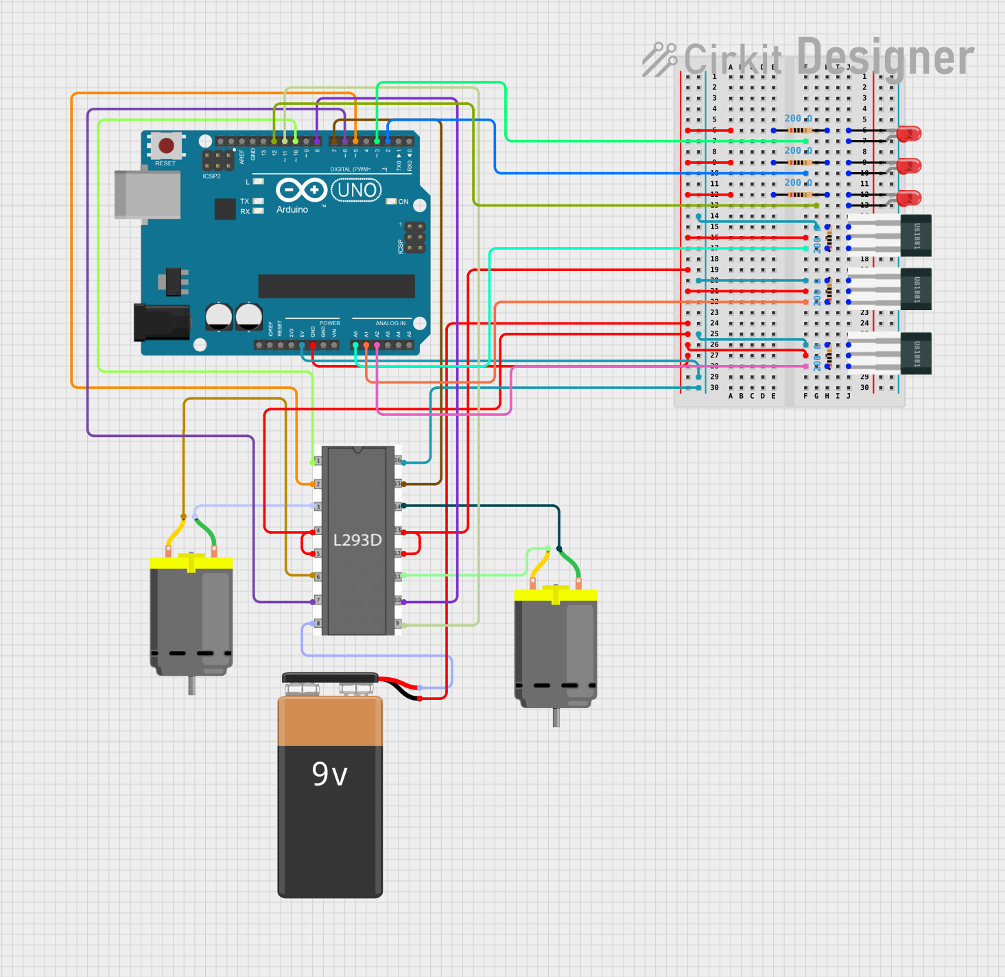
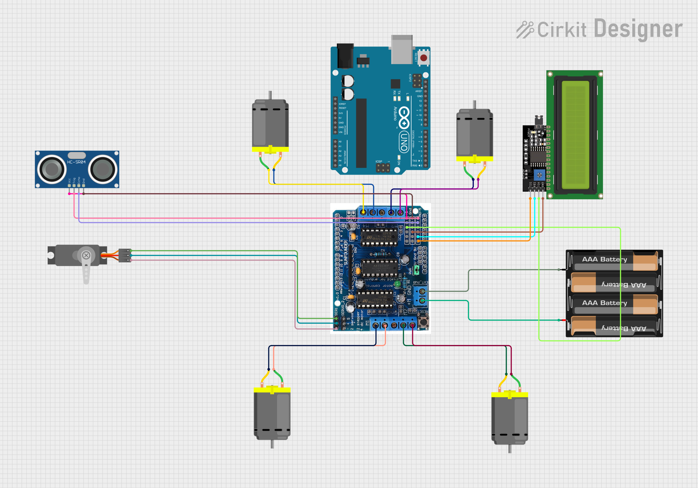

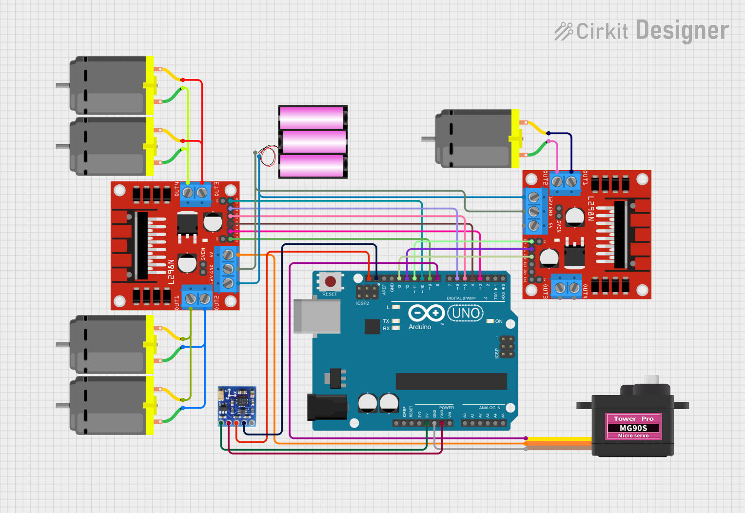
Explore Projects Built with L293D Motor Driver
Common Applications
- Robotics (e.g., controlling robot wheels)
- Conveyor belt systems
- Automated gates and doors
- Stepper motor control in CNC machines
- DIY motorized projects
Technical Specifications
The L293D is a robust IC with the following key specifications:
| Parameter | Value |
|---|---|
| Operating Voltage | 4.5V to 36V |
| Logic Input Voltage | 0V to 7V |
| Output Current (per channel) | 600mA (continuous), 1.2A (peak) |
| Number of Channels | 2 (dual H-bridge) |
| Maximum Power Dissipation | 5W |
| Enable Pins | Supports PWM for speed control |
| Operating Temperature | -40°C to +150°C |
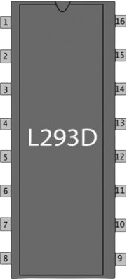
Pin Configuration and Descriptions
The L293D has 16 pins, as described in the table below:
| Pin Number | Pin Name | Description |
|---|---|---|
| 1 | Enable 1 (EN1) | Enables/Disables Motor 1. Can be used for PWM speed control. |
| 2 | Input 1 (IN1) | Logic input to control Motor 1 direction. |
| 3 | Output 1 (OUT1) | Output connected to one terminal of Motor 1. |
| 4 | GND | Ground (common ground for logic and motor power). |
| 5 | GND | Ground (common ground for logic and motor power). |
| 6 | Output 2 (OUT2) | Output connected to the other terminal of Motor 1. |
| 7 | Input 2 (IN2) | Logic input to control Motor 1 direction. |
| 8 | Vcc2 (Motor Vcc) | Power supply for motors (4.5V to 36V). |
| 9 | Enable 2 (EN2) | Enables/Disables Motor 2. Can be used for PWM speed control. |
| 10 | Input 3 (IN3) | Logic input to control Motor 2 direction. |
| 11 | Output 3 (OUT3) | Output connected to one terminal of Motor 2. |
| 12 | GND | Ground (common ground for logic and motor power). |
| 13 | GND | Ground (common ground for logic and motor power). |
| 14 | Output 4 (OUT4) | Output connected to the other terminal of Motor 2. |
| 15 | Input 4 (IN4) | Logic input to control Motor 2 direction. |
| 16 | Vcc1 (Logic Vcc) | Power supply for logic circuit (5V). |
Usage Instructions
How to Use the L293D in a Circuit
Power Connections:
- Connect
Vcc1(Pin 16) to a 5V power supply for the logic circuit. - Connect
Vcc2(Pin 8) to the motor power supply (4.5V to 36V, depending on the motor). - Connect all
GNDpins (Pins 4, 5, 12, 13) to the ground of the power supply.
- Connect
Motor Connections:
- Connect the motor terminals to the output pins (
OUT1,OUT2for Motor 1;OUT3,OUT4for Motor 2).
- Connect the motor terminals to the output pins (
Control Logic:
- Use the input pins (
IN1,IN2for Motor 1;IN3,IN4for Motor 2) to control the direction of the motors. - Use the enable pins (
EN1for Motor 1;EN2for Motor 2) to enable/disable the motors or to control speed using PWM.
- Use the input pins (
Direction Control:
- Set the input pins as follows to control motor direction:
IN1 = HIGH,IN2 = LOW: Motor 1 moves forward.IN1 = LOW,IN2 = HIGH: Motor 1 moves backward.IN1 = IN2: Motor 1 stops.
- Set the input pins as follows to control motor direction:
Speed Control:
- Apply a PWM signal to the enable pins (
EN1orEN2) to control motor speed.
- Apply a PWM signal to the enable pins (
Example: Connecting L293D to Arduino UNO
Below is an example of how to control a DC motor using the L293D and Arduino UNO:
// Define motor control pins
const int ENA = 9;  // Enable pin for Motor 1 (connected to PWM pin)
const int IN1 = 2;  // Input 1 for Motor 1
const int IN2 = 3;  // Input 2 for Motor 1

void setup() {
  // Set motor control pins as outputs
  pinMode(ENA, OUTPUT);
  pinMode(IN1, OUTPUT);
  pinMode(IN2, OUTPUT);
}

void loop() {
  // Move motor forward
  digitalWrite(IN1, HIGH);  // Set IN1 HIGH
  digitalWrite(IN2, LOW);   // Set IN2 LOW
  analogWrite(ENA, 200);    // Set speed (0-255)

  delay(2000);              // Run for 2 seconds

  // Stop motor
  digitalWrite(IN1, LOW);   // Set IN1 LOW
  digitalWrite(IN2, LOW);   // Set IN2 LOW
  analogWrite(ENA, 0);      // Set speed to 0

  delay(1000);              // Wait for 1 second

  // Move motor backward
  digitalWrite(IN1, LOW);   // Set IN1 LOW
  digitalWrite(IN2, HIGH);  // Set IN2 HIGH
  analogWrite(ENA, 150);    // Set speed (0-255)

  delay(2000);              // Run for 2 seconds

  // Stop motor
  digitalWrite(IN1, LOW);
  digitalWrite(IN2, LOW);
  analogWrite(ENA, 0);

  delay(1000);              // Wait for 1 second
}
Important Considerations
- Ensure the motor power supply voltage matches the motor's specifications.
- Use a heat sink if the IC gets too hot during operation.
- Avoid exceeding the maximum current rating to prevent damage to the IC.
- Decouple the power supply with capacitors to reduce noise and voltage spikes.
Troubleshooting and FAQs
Common Issues and Solutions
Motor Not Running:
- Check power supply connections to
Vcc1andVcc2. - Ensure the enable pin (
EN1orEN2) is set to HIGH or receiving a PWM signal. - Verify the input logic pins (
IN1,IN2, etc.) are correctly configured.
- Check power supply connections to
Motor Running in the Wrong Direction:
- Reverse the logic levels on the input pins (e.g., swap
IN1andIN2).
- Reverse the logic levels on the input pins (e.g., swap
IC Overheating:
- Ensure the current drawn by the motor does not exceed 600mA.
- Use a heat sink or reduce the motor load.
PWM Speed Control Not Working:
- Verify the PWM signal is being sent to the correct enable pin.
- Check the PWM frequency and duty cycle settings in your microcontroller code.
FAQs
Q: Can the L293D drive stepper motors?
A: Yes, the L293D can drive stepper motors by controlling the sequence of inputs to the H-bridges.
Q: Can I use the L293D with a 3.3V microcontroller?
A: The L293D requires a minimum logic voltage of 4.5V. Use a level shifter or a 5V microcontroller for compatibility.
Q: How many motors can the L293D control?
A: The L293D can control two DC motors or one stepper motor.