How to Use Fermion I2S MEMS Microphone : Examples, Pinouts, and Specs
Introduction
The Fermion I2S MEMS Microphone is a high-performance digital microphone that leverages Micro-Electro-Mechanical Systems (MEMS) technology. It is designed to capture high-quality audio signals and output them in a digital format using the I2S (Inter-IC Sound) interface. This makes it an ideal choice for applications requiring precise audio input, such as voice recognition systems, audio recording devices, and IoT applications.
Explore Projects Built with Fermion I2S MEMS Microphone
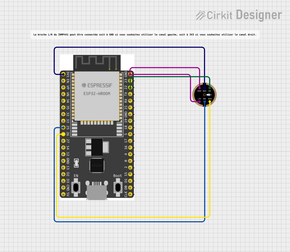
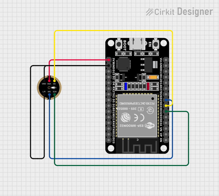
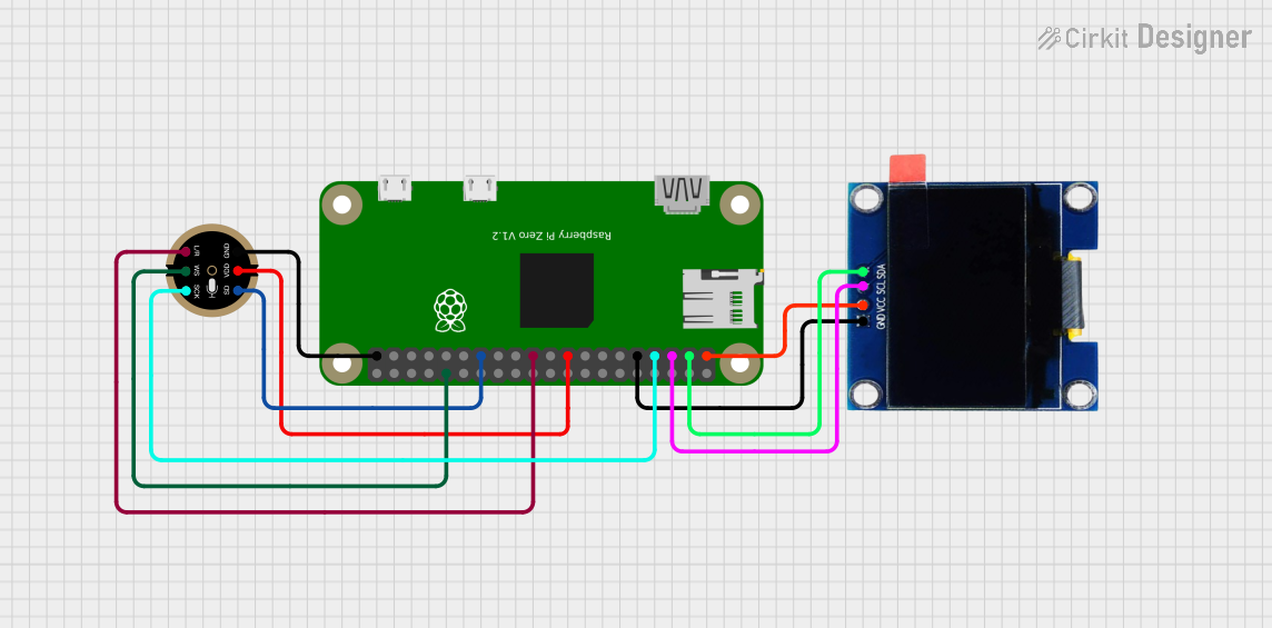
Explore Projects Built with Fermion I2S MEMS Microphone
Common Applications and Use Cases
- Voice-controlled devices (e.g., smart speakers, voice assistants)
- Audio recording and streaming systems
- IoT devices with audio input capabilities
- Noise monitoring and sound level detection
- Embedded systems requiring compact and efficient audio solutions
Technical Specifications
The Fermion I2S MEMS Microphone is designed for ease of integration and high performance. Below are its key technical details:
Key Technical Details
- Operating Voltage: 1.8V to 3.6V
- Current Consumption: < 1 mA (typical)
- Output Format: I2S digital audio
- Frequency Response: 50 Hz to 20 kHz
- Signal-to-Noise Ratio (SNR): 64 dB
- Sensitivity: -26 dBFS ±3 dB
- Directionality: Omnidirectional
- Operating Temperature: -40°C to +85°C
- Dimensions: 3.5 mm × 2.65 mm × 0.98 mm
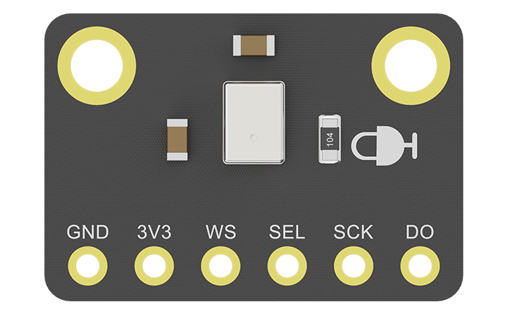
Pin Configuration and Descriptions
The Fermion I2S MEMS Microphone has a simple pinout for easy integration. Below is the pin configuration:
| Pin Name | Pin Type | Description |
|---|---|---|
| VDD | Power Input | Power supply pin. Connect to a voltage source between 1.8V and 3.6V. |
| GND | Ground | Ground pin. Connect to the ground of the circuit. |
| WS | Input | Word Select (WS) pin. Used to indicate left or right channel in I2S communication. |
| SCK | Input | Serial Clock (SCK) pin. Provides the clock signal for I2S communication. |
| SD | Output | Serial Data (SD) pin. Outputs the digital audio data in I2S format. |
Usage Instructions
The Fermion I2S MEMS Microphone is straightforward to use in digital audio applications. Below are the steps and considerations for integrating it into your circuit:
How to Use the Component in a Circuit
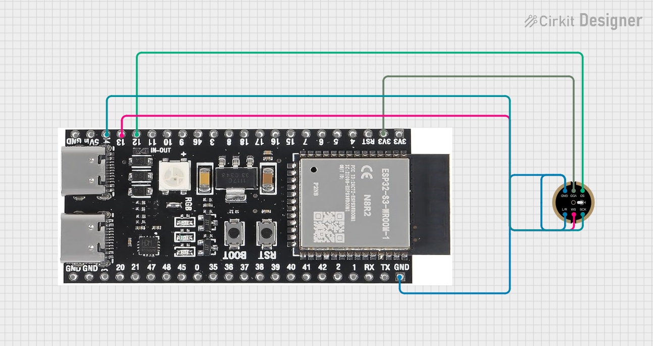
- Power the Microphone: Connect the VDD pin to a 1.8V–3.6V power source and the GND pin to the ground.
- Connect I2S Interface:
- Connect the WS pin to the Word Select line of your I2S master device.
- Connect the SCK pin to the Serial Clock line of your I2S master device.
- Connect the SD pin to the Serial Data input of your I2S master device.
- Configure the I2S Master: Ensure the I2S master device (e.g., microcontroller or processor) is configured to match the microphone's I2S settings (e.g., clock frequency, data format).
- Test the Audio Output: Use an audio processing library or software to process the digital audio data received from the microphone.
Important Considerations and Best Practices
- Clock Signal: Ensure the I2S clock signal (SCK) is stable and within the microphone's supported range.
- Power Supply: Use a low-noise power supply to avoid introducing noise into the audio signal.
- PCB Layout: Place the microphone away from high-frequency components to minimize interference.
- Orientation: The microphone is omnidirectional, but its placement can still affect audio quality. Test different placements for optimal performance.
Example Code for Arduino UNO
The Fermion I2S MEMS Microphone can be used with an Arduino UNO and an I2S-compatible shield or breakout board. Below is an example code snippet to capture audio data:
#include <I2S.h> // Include the I2S library for Arduino

void setup() {
  Serial.begin(9600); // Initialize serial communication for debugging
  while (!Serial);

  // Initialize I2S in receive mode
  if (!I2S.begin(I2S_PHILIPS_MODE, 44100, 32)) {
    Serial.println("Failed to initialize I2S!");
    while (1); // Halt if I2S initialization fails
  }

  Serial.println("I2S initialized successfully!");
}

void loop() {
  // Check if audio data is available
  if (I2S.available()) {
    int sample = I2S.read(); // Read a single audio sample
    Serial.println(sample); // Print the sample value for debugging
  }
}
Notes on the Code
- The code initializes the I2S interface in Philips mode with a 44.1 kHz sample rate and 32-bit data.
- Ensure your Arduino board supports I2S communication (e.g., Arduino MKR series or an external I2S shield for Arduino UNO).
Troubleshooting and FAQs
Common Issues Users Might Face
No Audio Output:
- Cause: Incorrect I2S configuration or wiring.
- Solution: Verify the I2S settings (e.g., clock frequency, data format) and check the connections.
Distorted Audio:
- Cause: Noisy power supply or interference from nearby components.
- Solution: Use a low-noise power supply and ensure proper PCB layout to minimize interference.
Microphone Not Detected:
- Cause: Faulty connections or damaged microphone.
- Solution: Check all connections and replace the microphone if necessary.
Solutions and Tips for Troubleshooting
- Verify Connections: Double-check all pin connections to ensure they match the pinout table.
- Test with Known Good Hardware: Use a different I2S master device to rule out issues with the microcontroller.
- Monitor Power Supply: Use an oscilloscope to check for noise or voltage drops on the VDD pin.
By following this documentation, you can successfully integrate and use the Fermion I2S MEMS Microphone in your projects.