How to Use xt-60: Examples, Pinouts, and Specs
Introduction
The XT60 is a high-current electrical connector widely used in RC (radio-controlled) applications, drones, electric vehicles, and other high-power systems. It is designed to handle up to 60A of continuous current, making it ideal for applications requiring reliable and efficient power delivery. The XT60 connector features a secure, polarized design that prevents reverse polarity connections, ensuring safe and consistent operation.
Explore Projects Built with xt-60
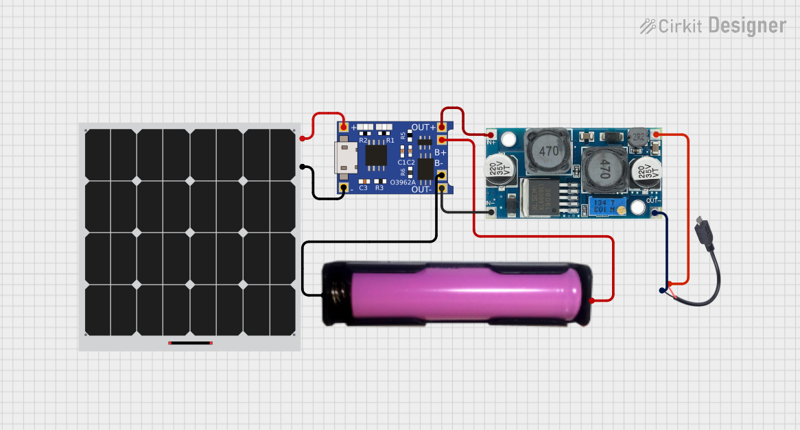


Explore Projects Built with xt-60
Common Applications and Use Cases
- RC vehicles (cars, planes, boats, and drones)
- Lithium Polymer (LiPo) battery connections
- Electric bikes and scooters
- High-current DC power systems
- DIY electronics projects requiring robust power connectors
Technical Specifications
The XT60 connector is designed to meet the demands of high-current applications while maintaining a compact and durable form factor. Below are the key technical details:
| Specification | Value |
|---|---|
| Rated Current | 60A (continuous) |
| Peak Current | 100A (for short durations) |
| Voltage Rating | Up to 500V DC |
| Contact Material | Gold-plated brass |
| Housing Material | Nylon (heat-resistant) |
| Operating Temperature | -20°C to 120°C |
| Connector Type | Male and Female (pair) |
| Wire Compatibility | 12 AWG to 10 AWG |
Pin Configuration and Descriptions
The XT60 connector consists of two main terminals: positive (+) and negative (-). These terminals are clearly marked on the connector housing to prevent incorrect connections.
| Pin | Description | Polarity |
|---|---|---|
| Pin 1 | Positive terminal | + |
| Pin 2 | Negative terminal | - |
Usage Instructions
How to Use the XT60 Connector in a Circuit
Soldering Wires to the XT60 Connector:
- Strip the insulation from the wire ends (12 AWG or 10 AWG recommended).
- Tin the exposed wire ends and the XT60 connector terminals with solder.
- Carefully solder the positive wire to the positive terminal and the negative wire to the negative terminal.
- Ensure the solder joints are clean and secure to prevent poor connections.
Connecting the XT60:
- Align the male and female connectors, ensuring the polarities match.
- Push the connectors together until they click into place, ensuring a secure connection.
Disconnecting the XT60:
- Firmly grip both connectors and pull them apart. Avoid pulling on the wires to prevent damage.
Important Considerations and Best Practices
- Avoid Overheating: When soldering, avoid overheating the connector housing, as excessive heat can deform the nylon material.
- Check Polarity: Always double-check the polarity markings before connecting to prevent reverse polarity damage.
- Use Heat Shrink Tubing: After soldering, cover the solder joints with heat shrink tubing to insulate and protect the connections.
- Secure Mounting: In high-vibration environments, secure the XT60 connectors to prevent accidental disconnections.
Example: Using XT60 with an Arduino UNO
While the XT60 is not directly connected to an Arduino UNO, it can be used to power the Arduino through a DC power supply or battery. Below is an example of powering an Arduino UNO using an XT60 connector and a LiPo battery:
/* Example: Powering Arduino UNO with XT60 and LiPo Battery
   - Ensure the LiPo battery voltage matches the Arduino's input voltage range.
   - Use a voltage regulator if necessary to step down the voltage.
*/

// No specific code is required for the XT60 connection itself.
// Simply connect the XT60 to the battery and ensure proper polarity.
// Use the Arduino's DC barrel jack or VIN pin for power input.
Troubleshooting and FAQs
Common Issues and Solutions
Loose Connection:
- Issue: The XT60 connectors do not fit tightly.
- Solution: Ensure the connectors are fully inserted. If the issue persists, inspect for wear or damage and replace the connector if necessary.
Overheating During Use:
- Issue: The connector becomes excessively hot during operation.
- Solution: Check for poor solder joints or undersized wires. Ensure the current does not exceed the rated 60A.
Reverse Polarity Connection:
- Issue: The device does not power on or is damaged after connection.
- Solution: Always verify the polarity markings before connecting. Use a multimeter to confirm the voltage and polarity of the power source.
Melted Housing During Soldering:
- Issue: The nylon housing deforms during soldering.
- Solution: Use a soldering iron with temperature control and limit the soldering time. Pre-tin the wires and terminals to reduce heat exposure.
FAQs
Q1: Can the XT60 handle more than 60A?
A1: The XT60 is rated for 60A continuous current, but it can handle up to 100A for short durations. Exceeding the rated current for extended periods may cause overheating or damage.
Q2: Is the XT60 waterproof?
A2: No, the XT60 is not waterproof. For outdoor or wet environments, consider using waterproof enclosures or connectors.
Q3: Can I use the XT60 with smaller gauge wires?
A3: Yes, but it is recommended to use 12 AWG or 10 AWG wires for optimal performance. Smaller wires may result in higher resistance and heat buildup.
Q4: Are XT60 connectors compatible with XT90 connectors?
A4: No, XT60 and XT90 connectors are not physically compatible due to differences in size and design.
By following this documentation, you can safely and effectively use the XT60 connector in your projects.