
How to Use 4 Ohm 3W Square Cavity Speaker: Examples, Pinouts, and Specs
 Design with 4 Ohm 3W Square Cavity Speaker in Cirkit Designer
Introduction
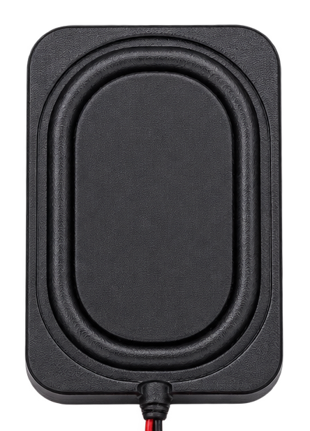
The 4 Ohm 3W Square Cavity Speaker (Manufacturer: Kznifmk, Part ID: 500754827A1) is a compact and efficient audio output device designed for small enclosures and portable electronics. With a 4 Ohm impedance and a power rating of 3 Watts, this speaker is ideal for delivering clear and crisp sound in applications such as laptops, tablets, handheld devices, and other compact systems. Its square cavity design ensures optimal sound resonance, making it suitable for high-quality audio reproduction in limited spaces.
Explore Projects Built with 4 Ohm 3W Square Cavity Speaker
 Open Project in Cirkit Designer
 Open Project in Cirkit Designer
 Open Project in Cirkit Designer
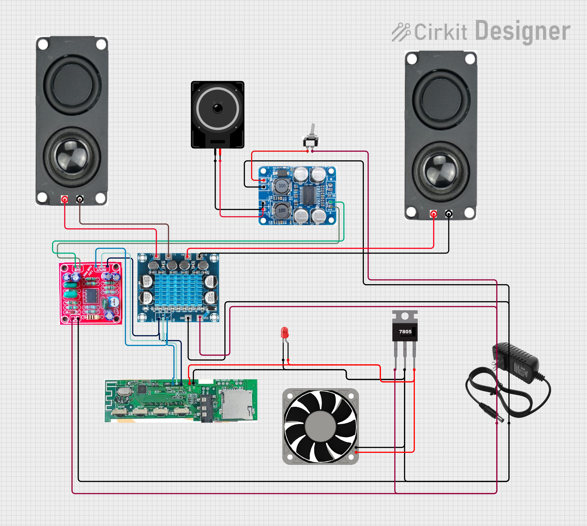 Open Project in Cirkit Designer
Explore Projects Built with 4 Ohm 3W Square Cavity Speaker
Open Project in Cirkit DesignerOpen Project in Cirkit DesignerOpen Project in Cirkit DesignerOpen Project in Cirkit DesignerCommon Applications
- Laptops and ultra-thin devices (e.g., Laptop 3525 series)
- Portable audio systems
- Embedded systems with audio output
- DIY electronics projects
- Smart home devices (e.g., voice assistants, alarms)
Technical Specifications
Key Specifications
| Parameter | Value |
|---|---|
| Manufacturer | Kznifmk |
| Part ID | 500754827A1 |
| Impedance | 4 Ohms |
| Power Rating | 3 Watts |
| Frequency Response | 200 Hz – 20 kHz |
| Sensitivity | 85 dB ± 3 dB |
| Dimensions | 40 mm x 40 mm x 10 mm |
| Weight | 15 grams |
| Connector Type | Solder pads |
| Enclosure Type | Square cavity |
Pin Configuration and Descriptions
The speaker does not have traditional pins but instead features solder pads for electrical connections. Below is a description of the solder pad configuration:
| Solder Pad | Description |
|---|---|
| Positive (+) | Connect to the positive terminal of the audio amplifier. |
| Negative (-) | Connect to the ground or negative terminal of the audio amplifier. |
Usage Instructions
How to Use the Speaker in a Circuit
Connect to an Audio Amplifier:
The speaker requires an audio amplifier to function correctly. Ensure the amplifier is compatible with the speaker's impedance (4 Ohms) and power rating (3 Watts).Soldering Connections:
- Identify the positive (+) and negative (-) solder pads on the speaker.
- Use a soldering iron to securely attach wires to the pads.
- Ensure proper polarity to avoid phase issues or sound distortion.
Mounting the Speaker:
- Place the speaker in a suitable enclosure to enhance sound quality.
- Use screws or adhesive to secure the speaker, ensuring it does not rattle during operation.
Testing the Speaker:
- Connect the speaker to the amplifier output.
- Play an audio signal to verify proper operation.
Important Considerations and Best Practices
- Power Handling: Do not exceed the 3W power rating to avoid damaging the speaker.
- Impedance Matching: Ensure the amplifier's output impedance matches the speaker's 4 Ohm impedance for optimal performance.
- Enclosure Design: Use a well-designed enclosure to improve sound quality and resonance.
- Avoid Overheating: Prolonged operation at high volumes may cause overheating. Allow adequate ventilation.
Example: Connecting to an Arduino UNO
To use the speaker with an Arduino UNO, you will need an audio amplifier module (e.g., PAM8403). Below is an example of how to generate a simple tone using the Arduino:
/*
  Example: Generate a tone on the 4 Ohm 3W Speaker
  Components:
  - Arduino UNO
  - PAM8403 Audio Amplifier Module
  - 4 Ohm 3W Speaker (Kznifmk 500754827A1)
*/

// Define the pin for the tone output
const int speakerPin = 9;

void setup() {
  // Initialize the speaker pin as an output
  pinMode(speakerPin, OUTPUT);
}

void loop() {
  // Generate a 1 kHz tone for 500 ms
  tone(speakerPin, 1000, 500);
  delay(1000); // Wait for 1 second before repeating
}
Note:
- The Arduino cannot directly drive the speaker. Always use an amplifier module to avoid damaging the microcontroller.
- Ensure proper connections between the amplifier, Arduino, and speaker.
Troubleshooting and FAQs
Common Issues and Solutions
| Issue | Possible Cause | Solution |
|---|---|---|
| No sound from the speaker | Incorrect wiring or loose connections | Verify solder joints and connections. |
| Distorted audio output | Overdriving the speaker or amplifier | Reduce the volume or input signal. |
| Low volume | Insufficient amplifier power | Use a higher-power amplifier. |
| Speaker overheating | Prolonged high-volume operation | Reduce volume and ensure ventilation. |
FAQs
Can I use this speaker without an amplifier?
No, the speaker requires an audio amplifier to function properly. Directly connecting it to a microcontroller or low-power source will not produce audible sound.What type of enclosure is recommended?
A sealed or ported enclosure designed for small speakers will enhance sound quality and bass response.Can I use this speaker for stereo applications?
Yes, you can use two speakers for stereo sound. Ensure each speaker is connected to a separate amplifier channel.What is the maximum safe operating temperature?
The speaker can operate safely up to 70°C. Avoid exposing it to higher temperatures to prevent damage.
This documentation provides all the necessary details to effectively use the 4 Ohm 3W Square Cavity Speaker in your projects. For further assistance, refer to the manufacturer's datasheet or contact Kznifmk support.