How to Use TEST PCB: Examples, Pinouts, and Specs
Introduction
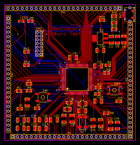
The TEST PCB, manufactured by MedVision (Part ID: Micro), is a versatile printed circuit board designed specifically for testing and evaluation purposes. It provides a reliable platform for troubleshooting, prototyping, and analyzing electronic circuits and components. The TEST PCB is an essential tool for engineers, technicians, and hobbyists working on circuit design and debugging.
Explore Projects Built with TEST PCB
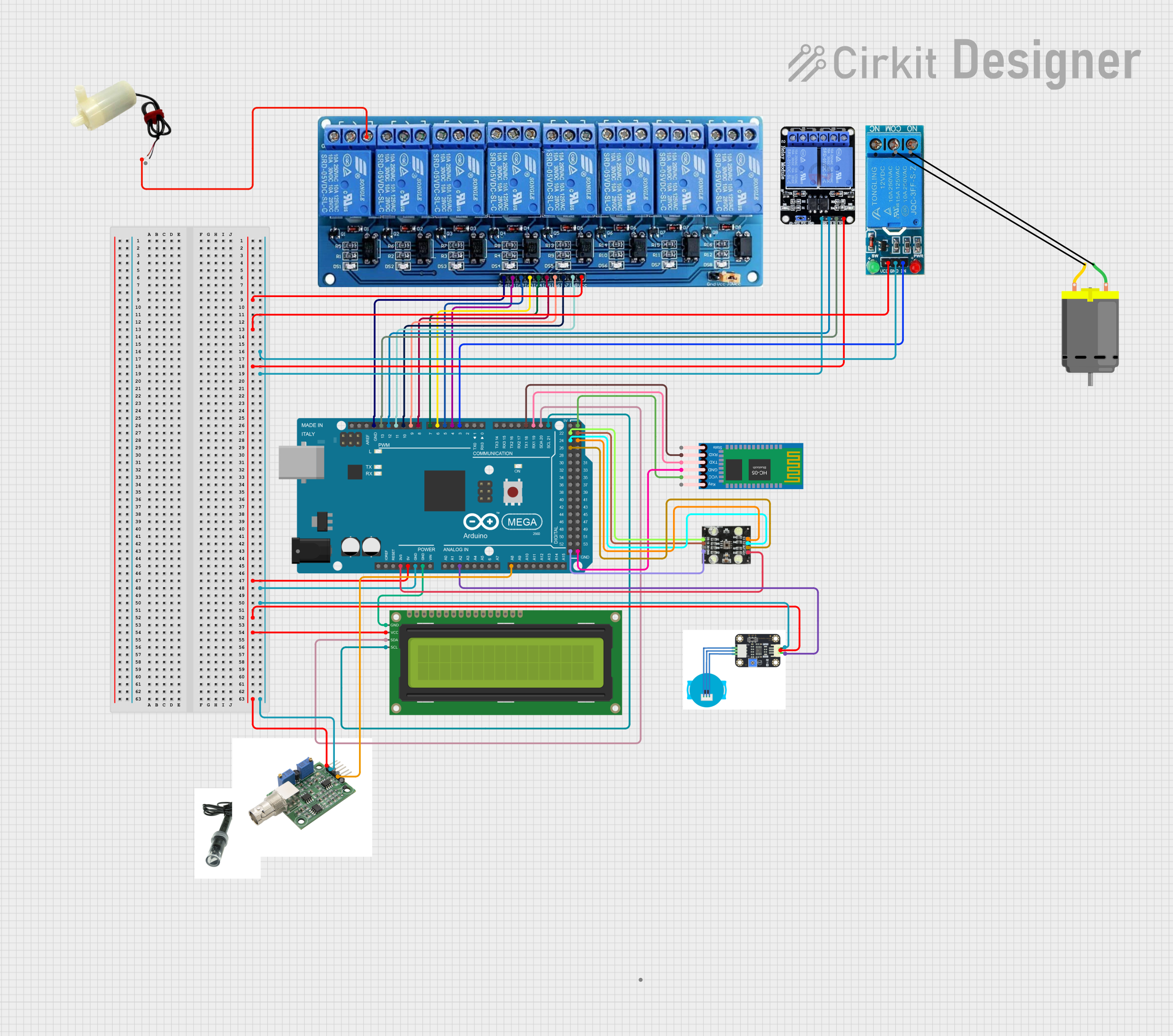
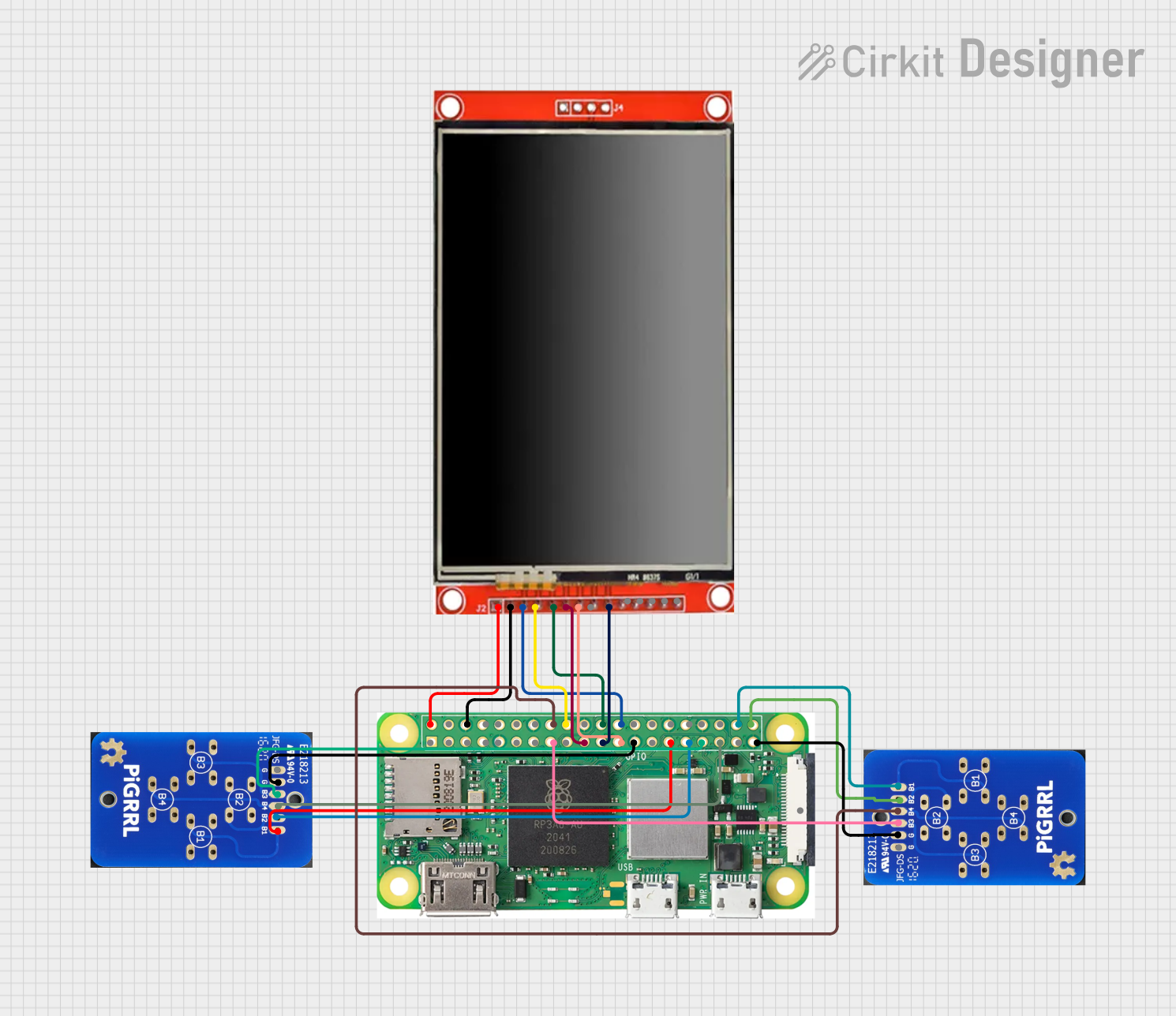
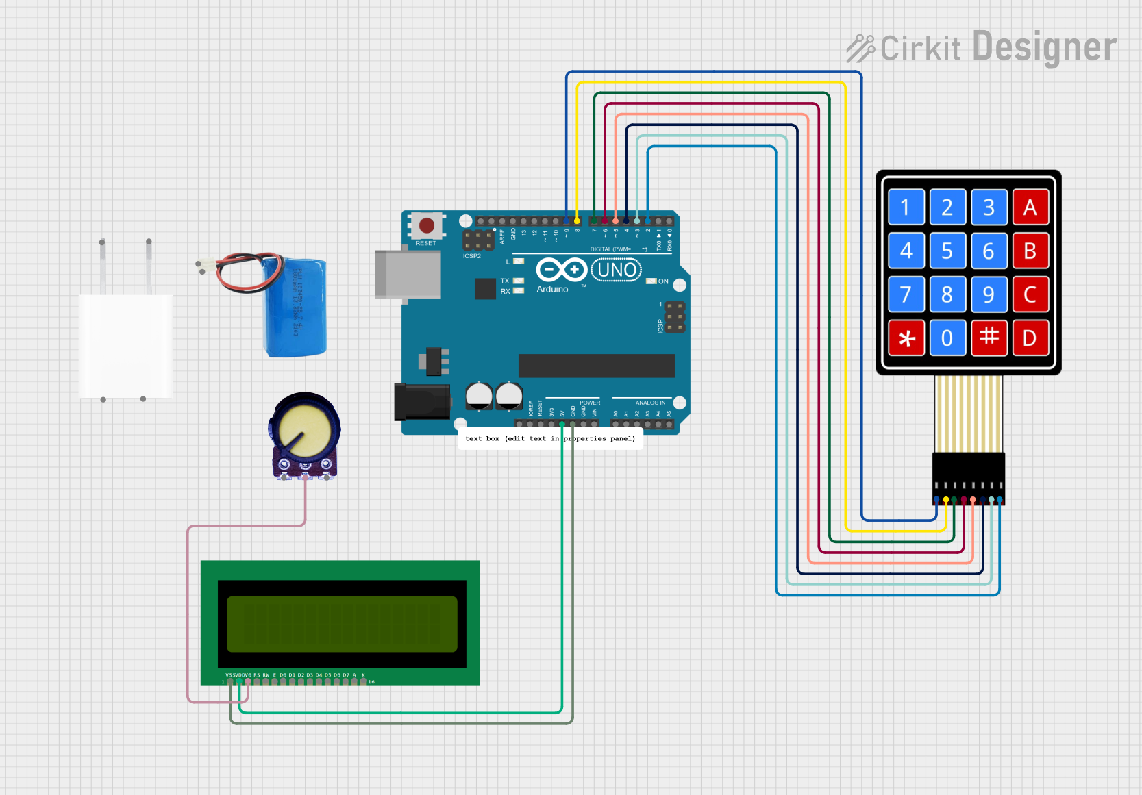
Explore Projects Built with TEST PCB
Common Applications and Use Cases
- Prototyping and testing new circuit designs
- Evaluating the performance of electronic components
- Debugging and troubleshooting faulty circuits
- Educational purposes for learning circuit design and analysis
- Temporary setups for experimental projects
Technical Specifications
The TEST PCB is designed to accommodate a wide range of electronic components and configurations. Below are its key technical details:
General Specifications
| Parameter | Specification |
|---|---|
| Manufacturer | MedVision |
| Part ID | Micro |
| PCB Material | FR4 (Flame Retardant 4) |
| PCB Thickness | 1.6 mm |
| Copper Layer Thickness | 35 µm (1 oz/ft²) |
| Dimensions | 100 mm x 80 mm |
| Operating Temperature | -40°C to 85°C |
| Solder Mask Color | Green |
| Surface Finish | HASL (Hot Air Solder Leveling) |
Pin Configuration and Descriptions
The TEST PCB features multiple connection points and test pads for easy integration with external components. Below is a description of the key pin headers and test points:
| Pin/Pad Label | Description |
|---|---|
| VCC | Power supply input (3.3V or 5V) |
| GND | Ground connection |
| IO1 - IO10 | General-purpose input/output (GPIO) pins |
| A1 - A4 | Analog input pins for signal testing |
| CLK | Clock signal input for timing applications |
| RST | Reset pin for connected circuits |
| TX, RX | UART communication pins for serial testing |
Usage Instructions
The TEST PCB is designed for ease of use, making it suitable for both beginners and experienced users. Follow the steps below to use the TEST PCB effectively:
Step 1: Powering the PCB
- Connect a regulated power supply (3.3V or 5V) to the
VCCpin. - Ensure the
GNDpin is connected to the ground of your power source.
Step 2: Connecting Components
- Solder or connect the components you wish to test to the appropriate pins or test pads.
- Use the GPIO pins (
IO1 - IO10) for digital signals and the analog pins (A1 - A4) for analog signals.
Step 3: Testing and Debugging
- Use a multimeter, oscilloscope, or logic analyzer to measure signals at the test points.
- For serial communication testing, connect the
TXandRXpins to a UART-compatible device.
Step 4: Using with Arduino UNO
The TEST PCB can be connected to an Arduino UNO for prototyping and testing. Below is an example code snippet for reading an analog signal from the A1 pin:
// Arduino code to read an analog signal from the TEST PCB
const int analogPin = A1; // Connect TEST PCB A1 pin to Arduino A1
int analogValue = 0;      // Variable to store the analog value

void setup() {
  Serial.begin(9600); // Initialize serial communication at 9600 baud
  pinMode(analogPin, INPUT); // Set A1 as an input
}

void loop() {
  analogValue = analogRead(analogPin); // Read the analog value
  Serial.print("Analog Value: ");      // Print the value to the Serial Monitor
  Serial.println(analogValue);
  delay(500); // Wait for 500ms before the next reading
}
Best Practices
- Always verify the power supply voltage before connecting to the
VCCpin. - Use proper ESD (Electrostatic Discharge) precautions when handling the PCB.
- Avoid short circuits by carefully inspecting solder joints and connections.
- Label your connections to avoid confusion during testing.
Troubleshooting and FAQs
Common Issues and Solutions
| Issue | Possible Cause | Solution |
|---|---|---|
| No power on the PCB | Incorrect power supply voltage | Verify the power supply and ensure it matches the required voltage (3.3V or 5V). |
| Signal not detected on pins | Loose or incorrect connections | Check all connections and ensure components are properly soldered or connected. |
| Serial communication not working | Incorrect baud rate or wiring | Verify the baud rate in the code and ensure TX and RX are correctly connected. |
| Overheating components | Excessive current draw | Check the circuit design and ensure components are within their rated specifications. |
FAQs
Q: Can I use the TEST PCB for high-frequency circuits?
A: The TEST PCB is suitable for low to moderate frequency applications. For high-frequency circuits, consider using a PCB with controlled impedance and specialized materials.
Q: Is the TEST PCB reusable?
A: Yes, the TEST PCB can be reused multiple times. However, excessive soldering and desoldering may degrade the pads over time.
Q: Can I use the TEST PCB with microcontrollers other than Arduino?
A: Absolutely! The TEST PCB is compatible with a wide range of microcontrollers, including Raspberry Pi, ESP32, and STM32.
By following this documentation, you can effectively utilize the TEST PCB for your testing and prototyping needs.