How to Use type C port: Examples, Pinouts, and Specs
Introduction
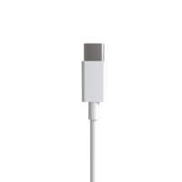
The USB Type-C port is a versatile 24-pin USB connector system, known for its two-fold rotationally-symmetrical design. This feature allows the connector to be inserted either way, enhancing user convenience. The Type-C port supports a wide range of protocols, including USB, HDMI, and DisplayPort, making it a popular choice for data transfer and power delivery in modern electronic devices.
Explore Projects Built with type C port


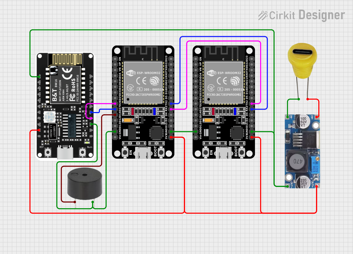
Explore Projects Built with type C port
Common Applications and Use Cases
- Smartphones and Tablets: For charging and data transfer.
- Laptops and Desktops: For connecting peripherals and external displays.
- Power Delivery: For charging devices with higher power requirements.
- Audio/Video Transmission: For connecting to HDMI and DisplayPort devices.
- Peripheral Devices: Such as external hard drives, USB hubs, and docking stations.
Technical Specifications
Key Technical Details
| Parameter | Value |
|---|---|
| Voltage Rating | 5V to 20V |
| Current Rating | Up to 5A |
| Power Delivery | Up to 100W |
| Data Transfer Rate | Up to 40 Gbps (USB 4.0) |
| Connector Type | 24-pin, reversible |
| Protocols Supported | USB, HDMI, DisplayPort, etc. |
Pin Configuration and Descriptions
| Pin Number | Name | Description |
|---|---|---|
| 1 | GND | Ground |
| 2 | TX1+ | Transmit Data Positive (SuperSpeed) |
| 3 | TX1- | Transmit Data Negative (SuperSpeed) |
| 4 | VBUS | Power Supply |
| 5 | CC1 | Configuration Channel 1 |
| 6 | D+ | Data Positive (USB 2.0) |
| 7 | D- | Data Negative (USB 2.0) |
| 8 | SBU1 | Sideband Use 1 |
| 9 | VBUS | Power Supply |
| 10 | RX2+ | Receive Data Positive (SuperSpeed) |
| 11 | RX2- | Receive Data Negative (SuperSpeed) |
| 12 | GND | Ground |
| 13 | GND | Ground |
| 14 | RX1+ | Receive Data Positive (SuperSpeed) |
| 15 | RX1- | Receive Data Negative (SuperSpeed) |
| 16 | VBUS | Power Supply |
| 17 | SBU2 | Sideband Use 2 |
| 18 | D- | Data Negative (USB 2.0) |
| 19 | D+ | Data Positive (USB 2.0) |
| 20 | CC2 | Configuration Channel 2 |
| 21 | VBUS | Power Supply |
| 22 | TX2- | Transmit Data Negative (SuperSpeed) |
| 23 | TX2+ | Transmit Data Positive (SuperSpeed) |
| 24 | GND | Ground |
Usage Instructions
How to Use the Component in a Circuit
Power Supply Connection:
- Connect the VBUS pins (4, 9, 16, 21) to the power supply (5V to 20V).
- Connect the GND pins (1, 12, 13, 24) to the ground of the circuit.
Data Transfer:
- For USB 2.0 data transfer, connect D+ (6, 19) and D- (7, 18) to the corresponding data lines.
- For SuperSpeed data transfer, connect TX1+ (2), TX1- (3), RX1+ (14), RX1- (15), TX2+ (23), TX2- (22), RX2+ (10), and RX2- (11) to the corresponding data lines.
Configuration Channels:
- Connect CC1 (5) and CC2 (20) to the configuration channel circuitry to detect the orientation and power delivery capabilities.
Sideband Use:
- Connect SBU1 (8) and SBU2 (17) for additional functionalities like audio or alternate modes.
Important Considerations and Best Practices
- Voltage and Current Ratings: Ensure that the power supply voltage and current ratings do not exceed the specified limits (5V to 20V, up to 5A).
- Proper Grounding: Properly ground the GND pins to avoid noise and potential damage to the circuit.
- Orientation Detection: Use the configuration channels (CC1 and CC2) to detect the orientation of the connector and configure the circuit accordingly.
- Heat Dissipation: Ensure adequate heat dissipation, especially when using the port for high power delivery (up to 100W).
Example: Connecting to an Arduino UNO
To connect a USB Type-C port to an Arduino UNO for data transfer, follow these steps:
- Connect the VBUS pin to the 5V pin on the Arduino UNO.
- Connect the GND pin to the GND pin on the Arduino UNO.
- Connect the D+ and D- pins to the corresponding data pins on the Arduino UNO.
// Example code to read data from a USB Type-C port connected to an Arduino UNO

void setup() {
  Serial.begin(9600); // Initialize serial communication at 9600 baud rate
}

void loop() {
  if (Serial.available() > 0) {
    // Read incoming data from the USB Type-C port
    char incomingData = Serial.read();
    // Print the incoming data to the Serial Monitor
    Serial.print("Received: ");
    Serial.println(incomingData);
  }
}
Troubleshooting and FAQs
Common Issues Users Might Face
No Power Delivery:
- Solution: Check the VBUS and GND connections. Ensure the power supply voltage is within the specified range.
Data Transfer Issues:
- Solution: Verify the connections of the D+, D-, TX, and RX pins. Ensure proper grounding and check for any loose connections.
Orientation Detection Failure:
- Solution: Ensure the CC1 and CC2 pins are correctly connected to the configuration channel circuitry.
Overheating:
- Solution: Ensure adequate heat dissipation and check the current draw to ensure it does not exceed the specified limit.
FAQs
Can I use the USB Type-C port for both power delivery and data transfer simultaneously?
- Yes, the USB Type-C port supports simultaneous power delivery and data transfer.
What is the maximum power delivery capability of the USB Type-C port?
- The USB Type-C port can deliver up to 100W of power.
Is the USB Type-C port compatible with older USB standards?
- Yes, the USB Type-C port is backward compatible with older USB standards.
How do I detect the orientation of the USB Type-C connector?
- Use the configuration channels (CC1 and CC2) to detect the orientation of the connector.
By following this documentation, users can effectively utilize the USB Type-C port in their electronic projects, ensuring proper connections and optimal performance.