How to Use VRX_SK7200: Examples, Pinouts, and Specs
Introduction
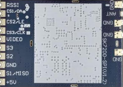
The VRX_SK7200 is a versatile RF receiver module manufactured by 123 with the part ID 1. It is designed for wireless communication applications and operates in the 2.4 GHz frequency range. This module is commonly used in remote control systems, telemetry, and other wireless data transmission systems due to its reliability and ease of integration.
Explore Projects Built with VRX_SK7200
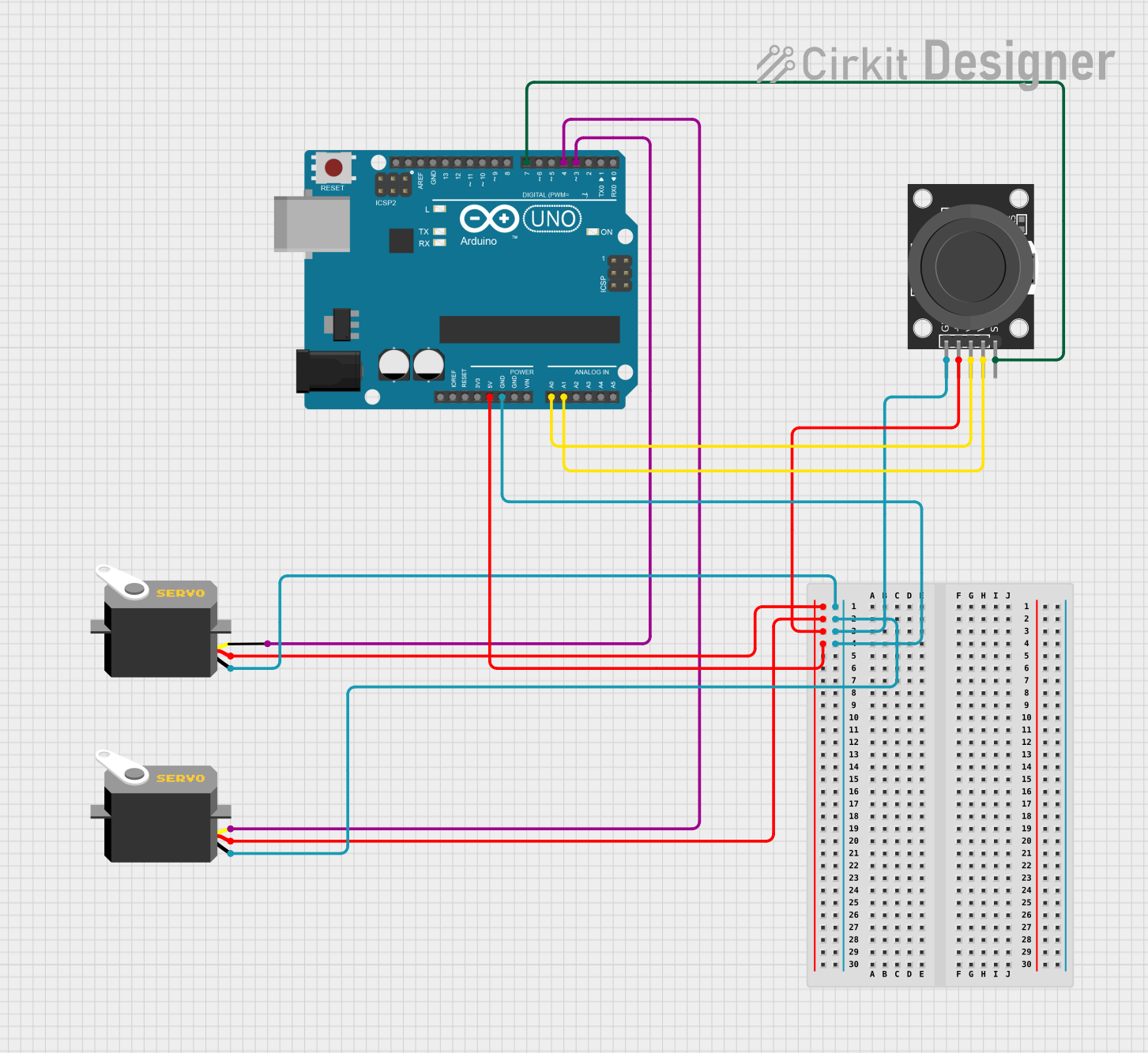
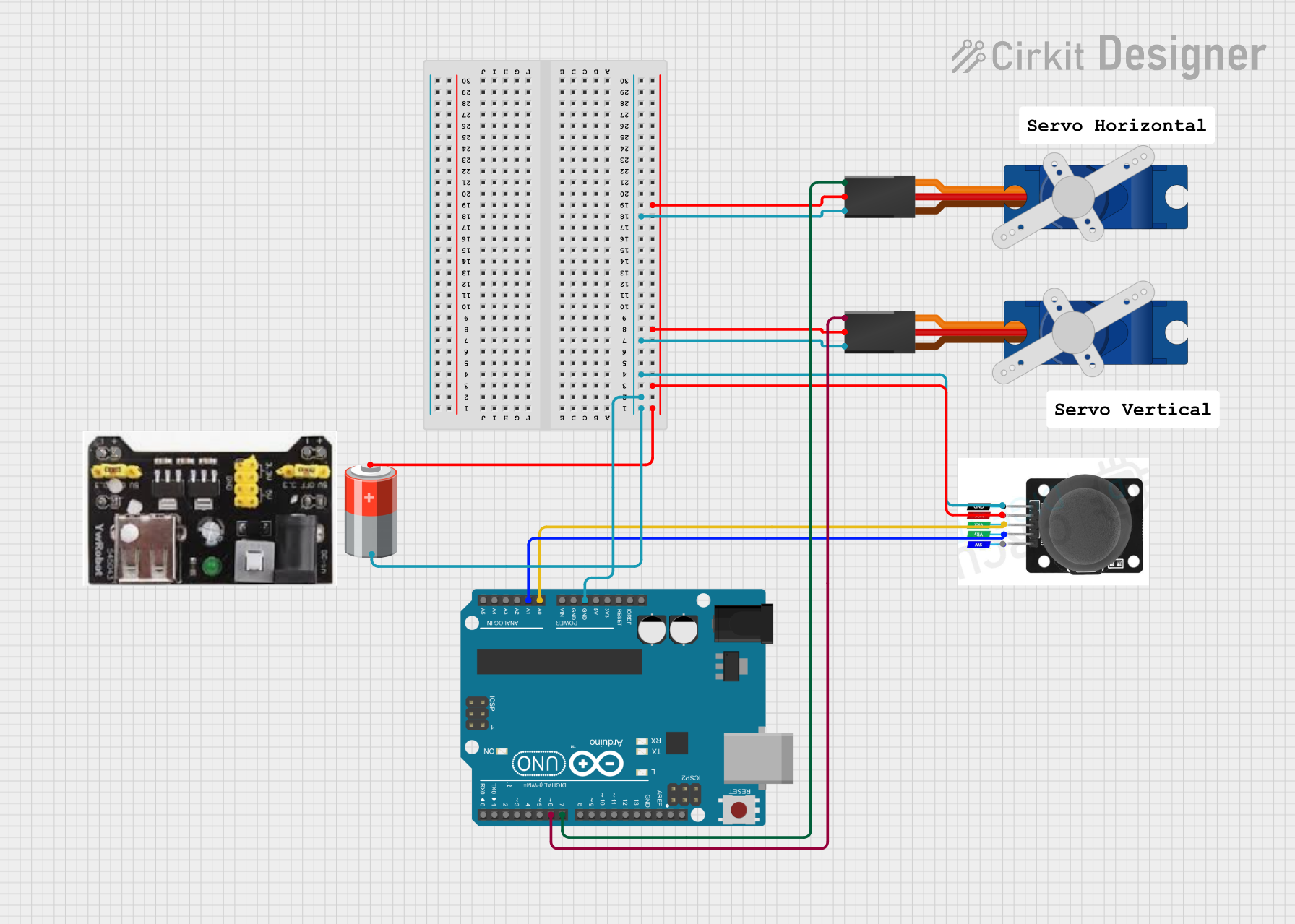
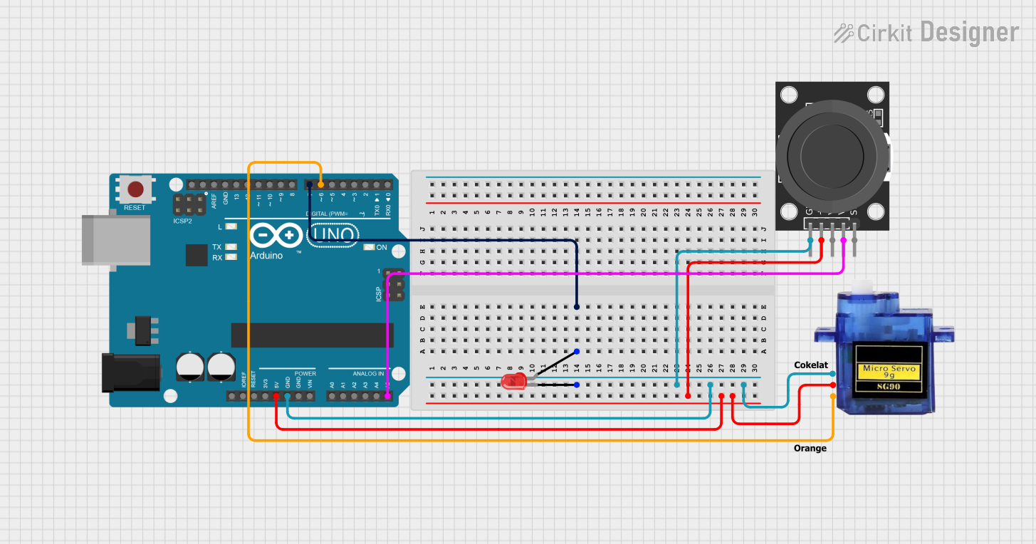
Explore Projects Built with VRX_SK7200
Common Applications
- Remote-controlled devices (e.g., drones, cars, and boats)
- Wireless telemetry systems
- IoT (Internet of Things) devices
- Wireless sensor networks
- Home automation systems
Technical Specifications
Key Technical Details
| Parameter | Value |
|---|---|
| Operating Frequency | 2.4 GHz |
| Supply Voltage | 3.3V to 5V |
| Current Consumption | 15 mA (typical) |
| Sensitivity | -95 dBm |
| Data Rate | Up to 2 Mbps |
| Modulation Type | GFSK (Gaussian Frequency Shift Keying) |
| Operating Temperature | -20°C to +70°C |
| Dimensions | 25 mm x 15 mm x 3 mm |
Pin Configuration and Descriptions
The VRX_SK7200 module has 8 pins. Below is the pinout and description:
| Pin Number | Pin Name | Description |
|---|---|---|
| 1 | VCC | Power supply input (3.3V to 5V) |
| 2 | GND | Ground |
| 3 | DATA_OUT | Digital output for received data |
| 4 | CSN | Chip Select Not (active low) |
| 5 | CE | Chip Enable (activates the module) |
| 6 | SCK | Serial Clock for SPI communication |
| 7 | MOSI | Master Out Slave In (SPI data input) |
| 8 | MISO | Master In Slave Out (SPI data output) |
Usage Instructions
How to Use the VRX_SK7200 in a Circuit
- Power Supply: Connect the VCC pin to a regulated 3.3V or 5V power source and the GND pin to the ground of your circuit.
- SPI Communication: Use the SCK, MOSI, and MISO pins to interface with a microcontroller via SPI protocol.
- Chip Enable: Set the CE pin high to activate the module for receiving data.
- Data Output: The received data will be available on the DATA_OUT pin.
- Chip Select: Use the CSN pin to enable or disable SPI communication with the module.
Important Considerations and Best Practices
- Ensure the power supply is stable and within the specified range (3.3V to 5V).
- Use decoupling capacitors (e.g., 0.1 µF) near the power pins to reduce noise.
- Keep the antenna area clear of obstructions for optimal signal reception.
- Use proper SPI settings: clock polarity (CPOL) = 0 and clock phase (CPHA) = 0.
- Avoid placing the module near high-frequency noise sources to prevent interference.
Example: Connecting VRX_SK7200 to Arduino UNO
Below is an example of how to connect the VRX_SK7200 to an Arduino UNO and read data:
Wiring Diagram
| VRX_SK7200 Pin | Arduino UNO Pin |
|---|---|
| VCC | 3.3V |
| GND | GND |
| DATA_OUT | Digital Pin 2 |
| CSN | Digital Pin 10 |
| CE | Digital Pin 9 |
| SCK | Digital Pin 13 |
| MOSI | Digital Pin 11 |
| MISO | Digital Pin 12 |
Arduino Code
#include <SPI.h>

// Define VRX_SK7200 pins
#define CE_PIN 9
#define CSN_PIN 10
#define DATA_OUT_PIN 2

void setup() {
  // Initialize serial communication for debugging
  Serial.begin(9600);

  // Set up SPI communication
  SPI.begin();
  pinMode(CE_PIN, OUTPUT);
  pinMode(CSN_PIN, OUTPUT);
  pinMode(DATA_OUT_PIN, INPUT);

  // Activate the module
  digitalWrite(CE_PIN, HIGH);
  digitalWrite(CSN_PIN, LOW);

  Serial.println("VRX_SK7200 initialized and ready to receive data.");
}

void loop() {
  // Read data from the DATA_OUT pin
  int receivedData = digitalRead(DATA_OUT_PIN);

  // Print the received data to the serial monitor
  Serial.print("Received Data: ");
  Serial.println(receivedData);

  delay(100); // Small delay for stability
}
Troubleshooting and FAQs
Common Issues and Solutions
No Data Received
- Cause: Incorrect wiring or SPI configuration.
- Solution: Double-check the wiring and ensure SPI settings (CPOL = 0, CPHA = 0) are correct.
Interference or Poor Signal Reception
- Cause: Obstructions near the antenna or nearby RF noise sources.
- Solution: Keep the antenna area clear and away from high-frequency noise sources.
Module Not Powering On
- Cause: Insufficient or unstable power supply.
- Solution: Ensure the power supply is within the 3.3V to 5V range and use decoupling capacitors.
Data Corruption
- Cause: High data rate or poor SPI communication.
- Solution: Reduce the data rate and ensure proper SPI connections.
FAQs
Q1: Can the VRX_SK7200 operate at 5V logic levels?
A1: Yes, the module supports both 3.3V and 5V logic levels, making it compatible with most microcontrollers.
Q2: What is the maximum range of the VRX_SK7200?
A2: The range depends on the environment and antenna used. In open spaces, it can achieve up to 100 meters.
Q3: Can I use multiple VRX_SK7200 modules in the same area?
A3: Yes, but ensure they operate on different channels to avoid interference.
Q4: Does the module require an external antenna?
A4: No, the module has an onboard antenna, but an external antenna can be added for extended range.