
How to Use thermal-magnetic circuit breaker 2A 2P: Examples, Pinouts, and Specs
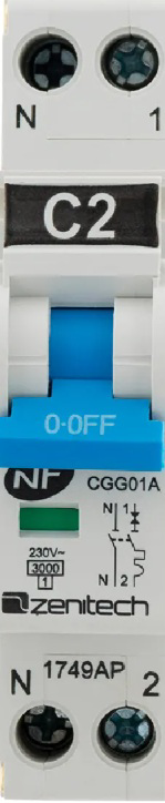
 Design with thermal-magnetic circuit breaker 2A 2P in Cirkit Designer
Introduction
A thermal-magnetic circuit breaker is a protective device designed to safeguard electrical circuits by automatically interrupting the flow of current when it detects an overload or short circuit. This dual-function breaker combines thermal protection (for prolonged overloads) and magnetic protection (for instantaneous short circuits). The 2A rating indicates that the breaker can handle a maximum current of 2 amperes, while the '2P' designation signifies that it has two poles, enabling it to disconnect both the live and neutral wires in a circuit.
Explore Projects Built with thermal-magnetic circuit breaker 2A 2P
 Open Project in Cirkit Designer
 Open Project in Cirkit Designer
 Open Project in Cirkit Designer
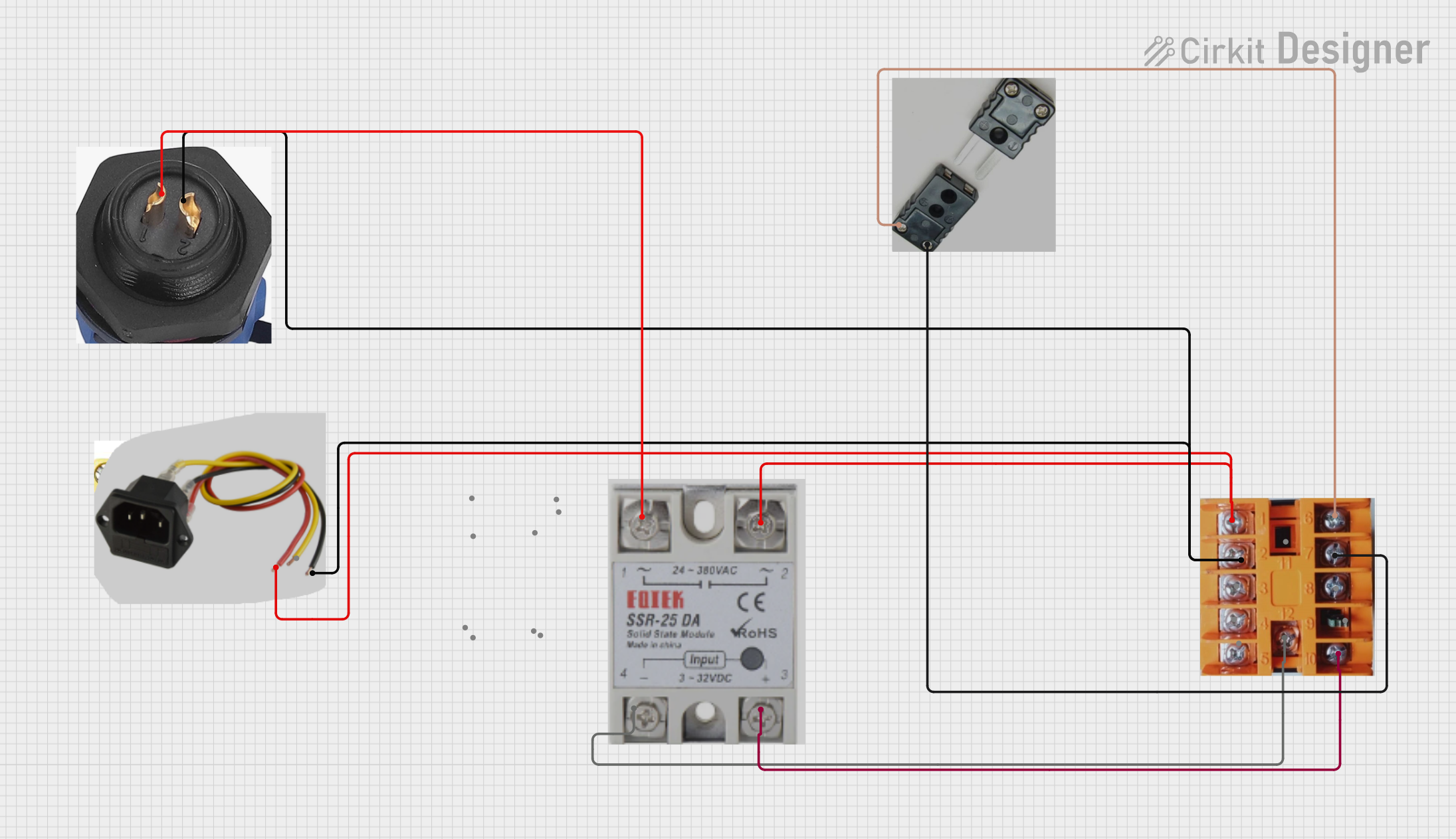 Open Project in Cirkit Designer
Explore Projects Built with thermal-magnetic circuit breaker 2A 2P
Open Project in Cirkit DesignerOpen Project in Cirkit DesignerOpen Project in Cirkit DesignerOpen Project in Cirkit DesignerCommon Applications and Use Cases
- Residential and commercial electrical panels for circuit protection
- Industrial machinery and equipment requiring dual-pole disconnection
- Protection of sensitive devices and low-current circuits
- Renewable energy systems, such as solar panel installations
- Motor control circuits and small-scale automation systems
Technical Specifications
Key Technical Details
| Parameter | Specification |
|---|---|
| Rated Current (In) | 2A |
| Number of Poles (2P) | 2 (disconnects live and neutral) |
| Rated Voltage (Un) | 230/400V AC |
| Breaking Capacity (Icu) | 6 kA |
| Trip Mechanism | Thermal (overload) and Magnetic (short circuit) |
| Operating Temperature Range | -5°C to +40°C |
| Mounting Type | DIN Rail |
| Standards Compliance | IEC 60898-1 |
Pin Configuration and Descriptions
| Pin/Terminal | Description |
|---|---|
| Terminal 1 | Input for live wire (Phase 1) |
| Terminal 2 | Input for neutral wire (Phase 2) |
| Terminal 3 | Output for live wire (Phase 1) |
| Terminal 4 | Output for neutral wire (Phase 2) |
Usage Instructions
How to Use the Component in a Circuit
- Mounting the Breaker: Secure the thermal-magnetic circuit breaker onto a standard DIN rail in your electrical panel.
- Wiring:
- Connect the live wire (Phase 1) to Terminal 1 and the neutral wire (Phase 2) to Terminal 2.
- Connect the load side wires to Terminal 3 (live output) and Terminal 4 (neutral output).
- Ensure all connections are tight and secure to prevent arcing or loose contacts.
- Power On: Once the wiring is complete, switch the breaker to the "ON" position to energize the circuit.
- Testing: Test the breaker by simulating an overload or short circuit to ensure it trips as expected.
Important Considerations and Best Practices
- Current Rating: Ensure the connected load does not exceed the 2A rating of the breaker.
- Proper Sizing: Use appropriately sized wires to handle the current without overheating.
- Environmental Conditions: Avoid installing the breaker in areas with excessive moisture, dust, or extreme temperatures.
- Resetting the Breaker: After a trip, identify and resolve the cause of the fault before resetting the breaker.
- Periodic Maintenance: Inspect the breaker periodically for signs of wear, corrosion, or damage.
Arduino UNO Integration
While thermal-magnetic circuit breakers are not directly interfaced with microcontrollers like the Arduino UNO, they can be used in circuits controlled by Arduino to protect connected devices. For example, you can use the breaker to safeguard a motor controlled by an Arduino.
Here is an example Arduino code to control a motor, with the breaker protecting the circuit:
// Example: Controlling a motor with Arduino UNO
// Ensure the thermal-magnetic circuit breaker is installed to protect the circuit.

const int motorPin = 9; // Pin connected to motor driver input

void setup() {
  pinMode(motorPin, OUTPUT); // Set motor pin as output
}

void loop() {
  digitalWrite(motorPin, HIGH); // Turn motor ON
  delay(5000); // Run motor for 5 seconds
  digitalWrite(motorPin, LOW); // Turn motor OFF
  delay(5000); // Wait for 5 seconds before restarting
}
Note: The breaker will trip if the motor draws more than 2A, protecting the circuit from damage.
Troubleshooting and FAQs
Common Issues Users Might Face
Breaker Trips Frequently:
- Cause: Overload or short circuit in the connected circuit.
- Solution: Check the load current and ensure it does not exceed 2A. Inspect the circuit for short circuits or faulty components.
Breaker Does Not Trip During Fault:
- Cause: Faulty breaker or improper installation.
- Solution: Verify the wiring and ensure the breaker is functioning correctly. Replace if necessary.
Difficulty Resetting the Breaker:
- Cause: Persistent fault in the circuit.
- Solution: Identify and resolve the fault before attempting to reset the breaker.
Overheating of Terminals:
- Cause: Loose connections or undersized wires.
- Solution: Tighten all connections and use wires of appropriate gauge.
Solutions and Tips for Troubleshooting
- Use a multimeter to measure the current and voltage in the circuit to identify faults.
- Ensure the breaker is compatible with the voltage and current requirements of your application.
- If the breaker trips repeatedly, consider upgrading to a higher-rated breaker if the load exceeds 2A (after verifying circuit requirements).
By following this documentation, you can effectively use the thermal-magnetic circuit breaker 2A 2P to protect your electrical circuits and ensure safe operation.