How to Use Adafruit OLED Color 1.5 inch 128x128 w microSD: Examples, Pinouts, and Specs
Introduction
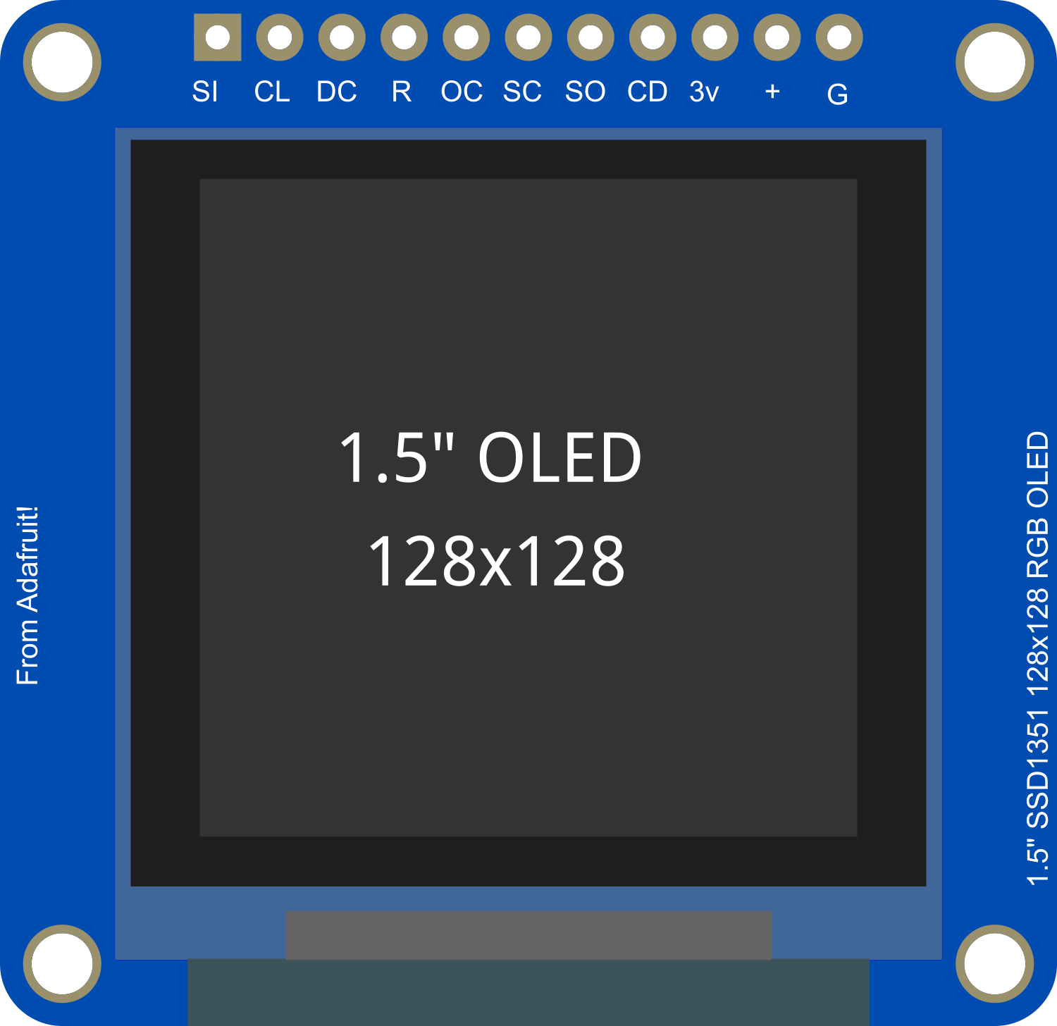
The Adafruit OLED Color 1.5 inch 128x128 w/ microSD is a compact and vibrant display module perfect for adding a small but high-resolution color screen to any microcontroller project. With its built-in microSD card slot, it offers additional storage options for displaying images or fonts. This display is commonly used in wearable tech, small handheld devices, and any application where space is at a premium but a high-quality display is required.
Explore Projects Built with Adafruit OLED Color 1.5 inch 128x128 w microSD
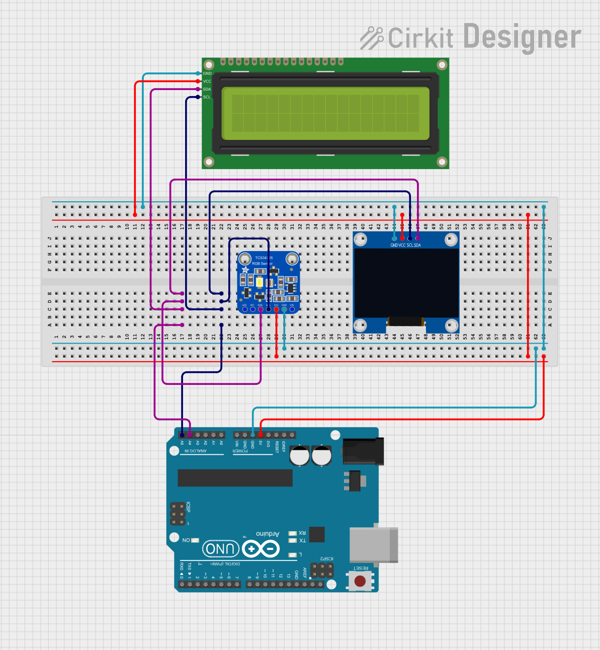


Explore Projects Built with Adafruit OLED Color 1.5 inch 128x128 w microSD
Common Applications and Use Cases
- Wearable devices
- Portable gaming systems
- Instrument panels
- User interfaces for small robotics projects
- Data visualization for sensors and other inputs
Technical Specifications
Key Technical Details
- Display Type: OLED
- Screen Size: 1.5 inches diagonal
- Resolution: 128x128 pixels
- Color Depth: 16-bit color, 65K colors
- Interface: SPI/I2C
- Operating Voltage: 3.3V - 5V
- Logic Level: 3.3V (5V tolerant)
- Current Draw: 40mA (typical)
Pin Configuration and Descriptions
| Pin Number | Pin Name | Description |
|---|---|---|
| 1 | GND | Ground |
| 2 | VCC | Power supply (3.3V - 5V) |
| 3 | SCL | Serial Clock Line (SPI/I2C clock) |
| 4 | SDA | Serial Data Line (SPI/I2C data) |
| 5 | RES | Reset pin |
| 6 | DC | Data/Command control pin (SPI only) |
| 7 | CS | Chip Select (SPI only) |
| 8 | SD_CS | microSD card slot Chip Select (SPI only) |
Usage Instructions
How to Use the Component in a Circuit
Powering the Display: Connect the VCC pin to a 3.3V or 5V power supply and the GND pin to the ground of your microcontroller.
Data Communication: For SPI communication, connect SCL to the SCK (clock) pin, SDA to the MOSI (data) pin, CS to your chosen chip select pin, and DC to your data/command control pin on your microcontroller. For I2C, connect SCL to the I2C clock and SDA to the I2C data pin.
Resetting the Display: The RES pin can be connected to a digital pin on your microcontroller to allow software control of resetting the display.
microSD Card Usage: To use the microSD card slot, connect the SD_CS pin to a digital pin on your microcontroller for chip select functionality.
Important Considerations and Best Practices
- Always ensure that the power supply is within the specified voltage range to prevent damage.
- Use a level shifter if your microcontroller operates at a different logic level than the display.
- When using SPI, remember to initialize the display with the correct data/command control pin and chip select pin.
- For optimal performance, use a high-quality microSD card and format it correctly before use.
Example Code for Arduino UNO
#include <Adafruit_GFX.h>    // Include core graphics library for the display
#include <Adafruit_SSD1351.h> // Include Adafruit SSD1351 OLED driver
#include <SPI.h>              // Include SPI library for communication

// Pin definitions for the Arduino UNO
#define SCLK_PIN 13
#define MOSI_PIN 11
#define CS_PIN   10
#define DC_PIN   9
#define RST_PIN  8
#define SD_CS_PIN 4

// Create an Adafruit_SSD1351 object
Adafruit_SSD1351 display = Adafruit_SSD1351(128, 128, &SPI, CS_PIN, DC_PIN, RST_PIN);

void setup() {
  display.begin(); // Initialize the display
  display.fillScreen(BLACK); // Clear the screen and set the background to black
}

void loop() {
  // Example: Draw a red rectangle
  display.drawRect(10, 10, 50, 50, RED);
  delay(500); // Wait for half a second
  // Example: Clear the screen
  display.fillScreen(BLACK);
  delay(500);
}
Ensure you have installed the Adafruit GFX and SSD1351 libraries before uploading this code to your Arduino UNO. The code initializes the display and then continuously draws and clears a red rectangle.
Troubleshooting and FAQs
Common Issues Users Might Face
- Display not powering on: Check the power connections and ensure the voltage is within the specified range.
- No image on the display: Verify that the SPI or I2C connections are correct and that the correct pins are defined in your code.
- Corrupted images when using microSD: Ensure the microSD card is formatted correctly and the SD_CS pin is correctly defined and used in your code.
Solutions and Tips for Troubleshooting
- Double-check all connections against the pin configuration table.
- Use example sketches provided by the library to test basic functionality.
- If using SPI, ensure that other SPI devices are not interfering with the display's operation.
FAQs
Q: Can I use this display with a 5V microcontroller? A: Yes, the display is 5V tolerant, but it is recommended to use a level shifter for long-term reliability.
Q: How do I store images on the microSD to display them? A: Images can be stored in a compatible format (e.g., BMP) and read using the SD library available in the Arduino IDE.
Q: What library should I use for this display? A: The Adafruit GFX library and Adafruit SSD1351 OLED driver are recommended for this display.
Q: Can I use this display for fast animations? A: While the display is capable of updating quickly, the speed of animations will also depend on the processing power of your microcontroller and the efficiency of your code.