
How to Use Adafruit LSM9DS1 9DoF Breakout: Examples, Pinouts, and Specs
 Design with Adafruit LSM9DS1 9DoF Breakout in Cirkit Designer
Introduction
The Adafruit LSM9DS1 9DoF Breakout (Part ID: 3387) is a compact sensor module that integrates a 3-axis accelerometer, 3-axis gyroscope, and 3-axis magnetometer. This combination provides 9 degrees of freedom (9DoF) for motion tracking and orientation sensing. The module is ideal for applications such as robotics, drones, wearable devices, and gaming systems, where precise motion and orientation data are critical.
The LSM9DS1 sensor communicates via I2C or SPI, making it compatible with a wide range of microcontrollers, including Arduino and Raspberry Pi. Its small form factor and versatile functionality make it a popular choice for hobbyists and professionals alike.
Explore Projects Built with Adafruit LSM9DS1 9DoF Breakout
 Open Project in Cirkit Designer
 Open Project in Cirkit Designer
 Open Project in Cirkit Designer
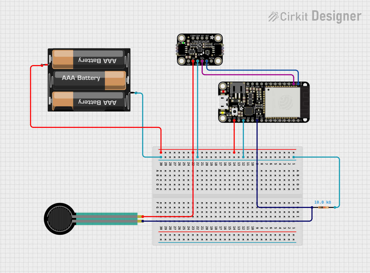 Open Project in Cirkit Designer
Explore Projects Built with Adafruit LSM9DS1 9DoF Breakout
Open Project in Cirkit DesignerOpen Project in Cirkit DesignerOpen Project in Cirkit DesignerOpen Project in Cirkit DesignerTechnical Specifications
Key Technical Details
- Manufacturer: Adafruit
- Part ID: 3387
- Sensor Type: 3-axis accelerometer, 3-axis gyroscope, 3-axis magnetometer
- Communication Protocols: I2C (default address: 0x6B for IMU, 0x1E for magnetometer) or SPI
- Operating Voltage: 3.3V to 5V
- Current Consumption: ~10mA (varies based on usage)
- Accelerometer Range: ±2g, ±4g, ±8g, ±16g
- Gyroscope Range: ±245 dps, ±500 dps, ±2000 dps
- Magnetometer Range: ±4 gauss, ±8 gauss, ±12 gauss, ±16 gauss
- Operating Temperature: -40°C to +85°C
- Dimensions: 20mm x 18mm x 3mm
Pin Configuration and Descriptions
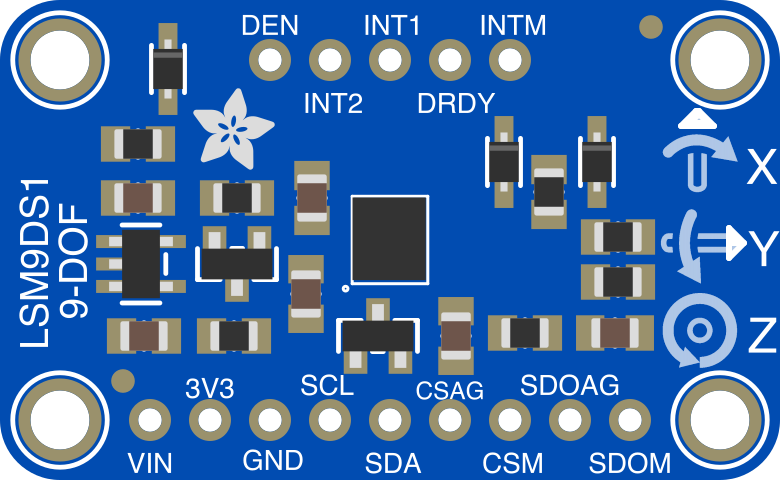
The Adafruit LSM9DS1 breakout board has the following pin layout:
| Pin | Name | Description |
|---|---|---|
| 1 | VIN | Power input (3.3V to 5V). Connect to the microcontroller's power supply. |
| 2 | GND | Ground. Connect to the ground of the microcontroller. |
| 3 | SCL | I2C clock line. Connect to the SCL pin of the microcontroller. |
| 4 | SDA | I2C data line. Connect to the SDA pin of the microcontroller. |
| 5 | CSAG | Chip select for accelerometer/gyroscope (used in SPI mode). |
| 6 | CSM | Chip select for magnetometer (used in SPI mode). |
| 7 | SDOAG | SPI data output for accelerometer/gyroscope. |
| 8 | SDOM | SPI data output for magnetometer. |
| 9 | INT1 | Interrupt pin 1 for accelerometer/gyroscope. |
| 10 | INT2 | Interrupt pin 2 for accelerometer/gyroscope. |
Usage Instructions
How to Use the Component in a Circuit
- Power the Sensor: Connect the VIN pin to a 3.3V or 5V power source and the GND pin to ground.
- Choose Communication Protocol:
- For I2C: Connect the SDA and SCL pins to the corresponding pins on your microcontroller.
- For SPI: Connect the CSAG, CSM, SDOAG, and SDOM pins as required for SPI communication.
- Install Required Libraries: If using Arduino, install the Adafruit LSM9DS1 library via the Arduino Library Manager.
- Write Code: Use the library functions to initialize the sensor, configure settings, and read data.
Important Considerations and Best Practices
- Voltage Compatibility: Ensure your microcontroller operates at 3.3V or 5V logic levels to avoid damaging the sensor.
- Pull-Up Resistors: If using I2C, ensure pull-up resistors are present on the SDA and SCL lines (typically 4.7kΩ).
- Sensor Orientation: Mount the sensor securely and in the correct orientation for accurate readings.
- Calibration: Perform calibration for the accelerometer, gyroscope, and magnetometer to improve accuracy.
Example Code for Arduino UNO
Below is an example of how to use the Adafruit LSM9DS1 with an Arduino UNO:
#include <Wire.h>
#include <Adafruit_Sensor.h>
#include <Adafruit_LSM9DS1.h>

// Create an instance of the LSM9DS1 sensor
Adafruit_LSM9DS1 lsm = Adafruit_LSM9DS1();

// Define I2C addresses for the sensor
#define LSM9DS1_XG_ADDRESS (0x6B) // Accelerometer/Gyroscope address
#define LSM9DS1_MAG_ADDRESS (0x1E) // Magnetometer address

void setup() {
  Serial.begin(115200); // Initialize serial communication
  while (!Serial) delay(10); // Wait for serial monitor to open

  // Initialize the sensor
  if (!lsm.begin()) {
    Serial.println("Failed to initialize LSM9DS1. Check wiring!");
    while (1);
  }
  Serial.println("LSM9DS1 initialized successfully!");

  // Set sensor ranges (optional)
  lsm.setupAccel(lsm.LSM9DS1_ACCELRANGE_2G); // Set accelerometer range to ±2g
  lsm.setupGyro(lsm.LSM9DS1_GYROSCALE_245DPS); // Set gyroscope range to ±245 dps
  lsm.setupMag(lsm.LSM9DS1_MAGGAIN_4GAUSS); // Set magnetometer range to ±4 gauss
}

void loop() {
  // Read accelerometer data
  sensors_event_t accel, gyro, mag;
  lsm.getEvent(&accel, &gyro, &mag);

  // Print accelerometer data
  Serial.print("Accel X: "); Serial.print(accel.acceleration.x); Serial.print(" m/s^2 ");
  Serial.print("Y: "); Serial.print(accel.acceleration.y); Serial.print(" m/s^2 ");
  Serial.print("Z: "); Serial.print(accel.acceleration.z); Serial.println(" m/s^2");

  // Print gyroscope data
  Serial.print("Gyro X: "); Serial.print(gyro.gyro.x); Serial.print(" rad/s ");
  Serial.print("Y: "); Serial.print(gyro.gyro.y); Serial.print(" rad/s ");
  Serial.print("Z: "); Serial.print(gyro.gyro.z); Serial.println(" rad/s");

  // Print magnetometer data
  Serial.print("Mag X: "); Serial.print(mag.magnetic.x); Serial.print(" uT ");
  Serial.print("Y: "); Serial.print(mag.magnetic.y); Serial.print(" uT ");
  Serial.print("Z: "); Serial.print(mag.magnetic.z); Serial.println(" uT");

  delay(500); // Delay for readability
}
Troubleshooting and FAQs
Common Issues
Sensor Not Detected:
- Ensure the wiring is correct and matches the chosen communication protocol.
- Verify the I2C addresses (0x6B and 0x1E) or SPI configuration.
- Check for loose connections or damaged wires.
Incorrect or No Data:
- Perform sensor calibration to improve accuracy.
- Ensure the sensor is mounted securely and not subject to vibrations.
Library Errors:
- Ensure the Adafruit LSM9DS1 library is installed and up to date.
- Verify that the correct board and port are selected in the Arduino IDE.
Solutions and Tips for Troubleshooting
- Use a multimeter to check for proper voltage levels at the VIN and GND pins.
- Test the I2C or SPI communication using a logic analyzer if available.
- Refer to the Adafruit LSM9DS1 library documentation for advanced configuration options.
By following this documentation, you can effectively integrate the Adafruit LSM9DS1 9DoF Breakout into your projects and troubleshoot common issues with ease.