Cirkit Designer Logo
Cirkit Designer
Your all-in-one circuit design IDE
Home / 
Component Documentation

How to Use Line Sensor: Examples, Pinouts, and Specs

Image of Line Sensor
Cirkit Designer LogoDesign with Line Sensor in Cirkit Designer

Introduction

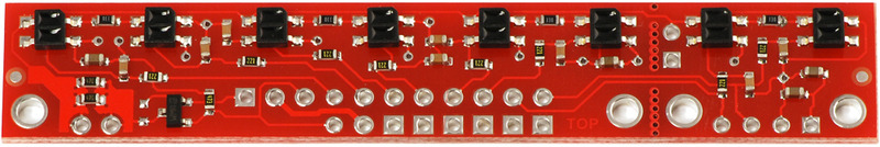
The QTR-8RC Reflectance Sensor Array by Pololu is an electronic component designed for line sensing, typically used in robotics for line-following tasks. It consists of eight infrared (IR) LED/phototransistor pairs that can be used to detect transitions from light to dark (lines) or even small variations in the reflective surface beneath the robot. This sensor is ideal for competitions and research projects where precise line detection is crucial.

Explore Projects Built with Line Sensor

Use Cirkit Designer to design, explore, and prototype these projects online. Some projects support real-time simulation. Click "Open Project" to start designing instantly!
ESP32-Controlled Line Sensor Interface
Image of line sensor: A project utilizing Line Sensor in a practical application
This circuit connects an ESP32 Wroom microcontroller to a Line Sensor for the purpose of detecting and processing line position data. The ESP32's GPIO32 and GPIO33 pins are interfaced with the Line Sensor's output pins, allowing the microcontroller to read sensor data. Power and ground connections are established between the ESP32 and the Line Sensor to provide the necessary operating voltage and common reference.
Cirkit Designer LogoOpen Project in Cirkit Designer
Arduino UNO-Based Line Following Robot with IR Obstacle Detection
Image of LINEFOLLOWER: A project utilizing Line Sensor in a practical application
This circuit is designed for a line-following or obstacle-avoiding robot, featuring an Arduino UNO microcontroller interfaced with a line sensor, two TCRT-5000 IR sensors for detecting obstacles, and an L298N motor driver to control two DC motors. The entire system is powered by two 18650 Li-ion batteries, and the Arduino's embedded code is responsible for processing sensor signals and managing motor control for navigation.
Cirkit Designer LogoOpen Project in Cirkit Designer
Arduino-Controlled Line-Following Robot with Ultrasonic Obstacle Detection
Image of RAD project: A project utilizing Line Sensor in a practical application
This circuit is designed for a line-following and obstacle-avoiding robot. It uses an Arduino UNO to control two DC motors via an L298N motor driver, based on input from IR sensors for line detection and an HC-SR04 ultrasonic sensor for distance measurement. The Arduino's firmware is programmed to adjust the robot's path in response to detected lines and obstacles, ensuring it follows a predetermined path while avoiding collisions.
Cirkit Designer LogoOpen Project in Cirkit Designer
Arduino UNO Line Following Robot with L298N Motor Driver and Battery Power
Image of Arduino-Controlled Line Following Robot with Dual DC Motors and L298N Driver: A project utilizing Line Sensor in a practical application
This circuit is a line-following robot controlled by an Arduino UNO. It uses a line sensor array to detect the path and an L298N motor driver to control two DC motors, enabling the robot to follow a line autonomously.
Cirkit Designer LogoOpen Project in Cirkit Designer

Explore Projects Built with Line Sensor

Use Cirkit Designer to design, explore, and prototype these projects online. Some projects support real-time simulation. Click "Open Project" to start designing instantly!
Image of line sensor: A project utilizing Line Sensor in a practical application
ESP32-Controlled Line Sensor Interface
This circuit connects an ESP32 Wroom microcontroller to a Line Sensor for the purpose of detecting and processing line position data. The ESP32's GPIO32 and GPIO33 pins are interfaced with the Line Sensor's output pins, allowing the microcontroller to read sensor data. Power and ground connections are established between the ESP32 and the Line Sensor to provide the necessary operating voltage and common reference.
Cirkit Designer LogoOpen Project in Cirkit Designer
Image of LINEFOLLOWER: A project utilizing Line Sensor in a practical application
Arduino UNO-Based Line Following Robot with IR Obstacle Detection
This circuit is designed for a line-following or obstacle-avoiding robot, featuring an Arduino UNO microcontroller interfaced with a line sensor, two TCRT-5000 IR sensors for detecting obstacles, and an L298N motor driver to control two DC motors. The entire system is powered by two 18650 Li-ion batteries, and the Arduino's embedded code is responsible for processing sensor signals and managing motor control for navigation.
Cirkit Designer LogoOpen Project in Cirkit Designer
Image of RAD project: A project utilizing Line Sensor in a practical application
Arduino-Controlled Line-Following Robot with Ultrasonic Obstacle Detection
This circuit is designed for a line-following and obstacle-avoiding robot. It uses an Arduino UNO to control two DC motors via an L298N motor driver, based on input from IR sensors for line detection and an HC-SR04 ultrasonic sensor for distance measurement. The Arduino's firmware is programmed to adjust the robot's path in response to detected lines and obstacles, ensuring it follows a predetermined path while avoiding collisions.
Cirkit Designer LogoOpen Project in Cirkit Designer
Image of Arduino-Controlled Line Following Robot with Dual DC Motors and L298N Driver: A project utilizing Line Sensor in a practical application
Arduino UNO Line Following Robot with L298N Motor Driver and Battery Power
This circuit is a line-following robot controlled by an Arduino UNO. It uses a line sensor array to detect the path and an L298N motor driver to control two DC motors, enabling the robot to follow a line autonomously.
Cirkit Designer LogoOpen Project in Cirkit Designer

Common Applications and Use Cases

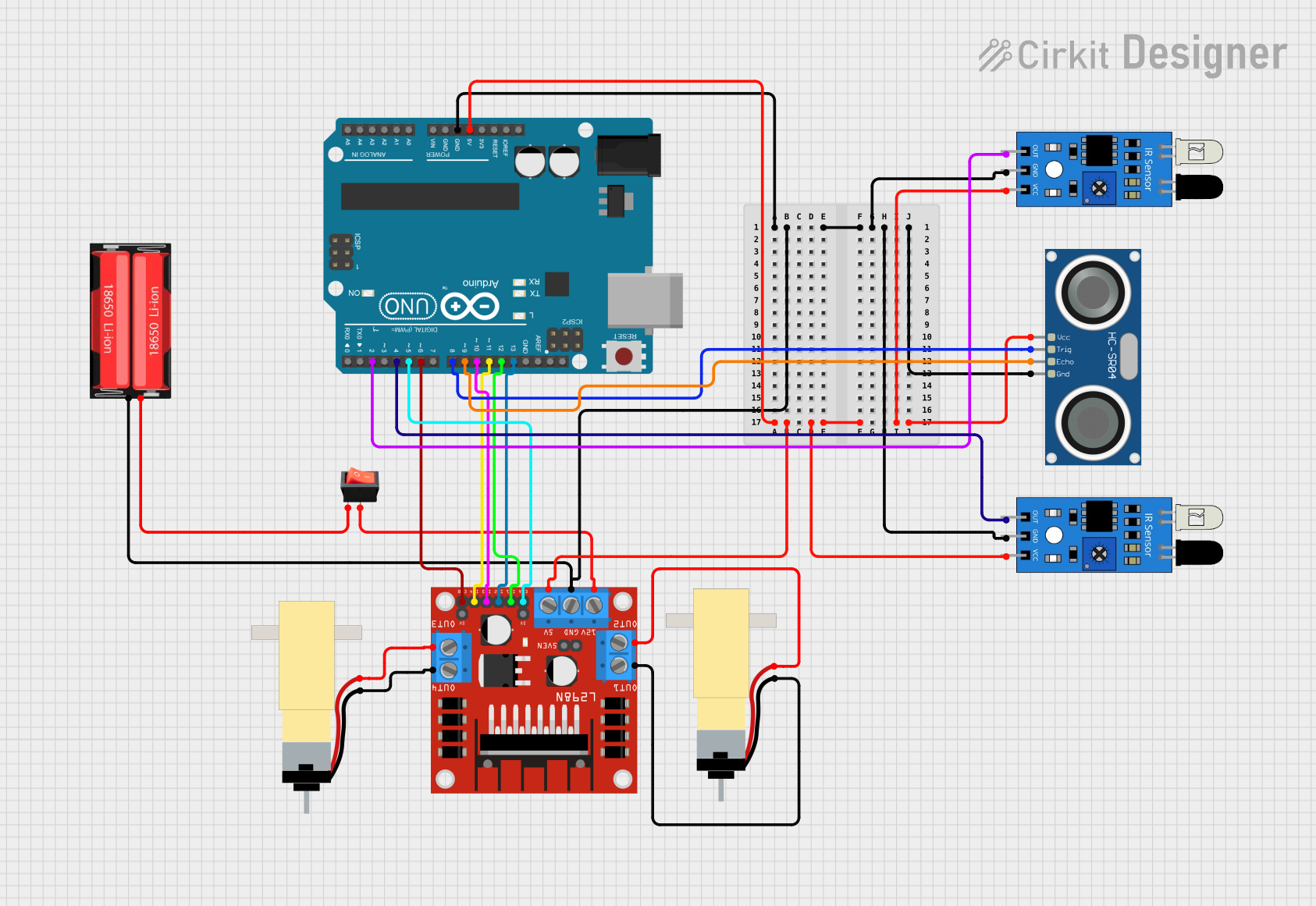
  • Line-following robots
  • Edge detection for avoiding table edges
  • Reading encoded signals in a track for advanced navigation

Technical Specifications

Key Technical Details

  • Operating Voltage: 3.3V to 5V
  • Average Current Consumption: 100 mA (typical when all LEDs are on)
  • Output Format: 8 digital I/O-compatible signals that can be read as a timed high pulse
  • Optimal Sensing Distance: 3 mm (0.125 inches)
  • Maximum Recommended Sensing Distance: 9.5 mm (0.375 inches)

Pin Configuration and Descriptions

Pin Number Description
1 VCC (3.3V to 5V)
2 GND
3 Sensor 1 Output
4 Sensor 2 Output
5 Sensor 3 Output
6 Sensor 4 Output
7 Sensor 5 Output
8 Sensor 6 Output
9 Sensor 7 Output
10 Sensor 8 Output
11 LEDON (Optional)

Usage Instructions

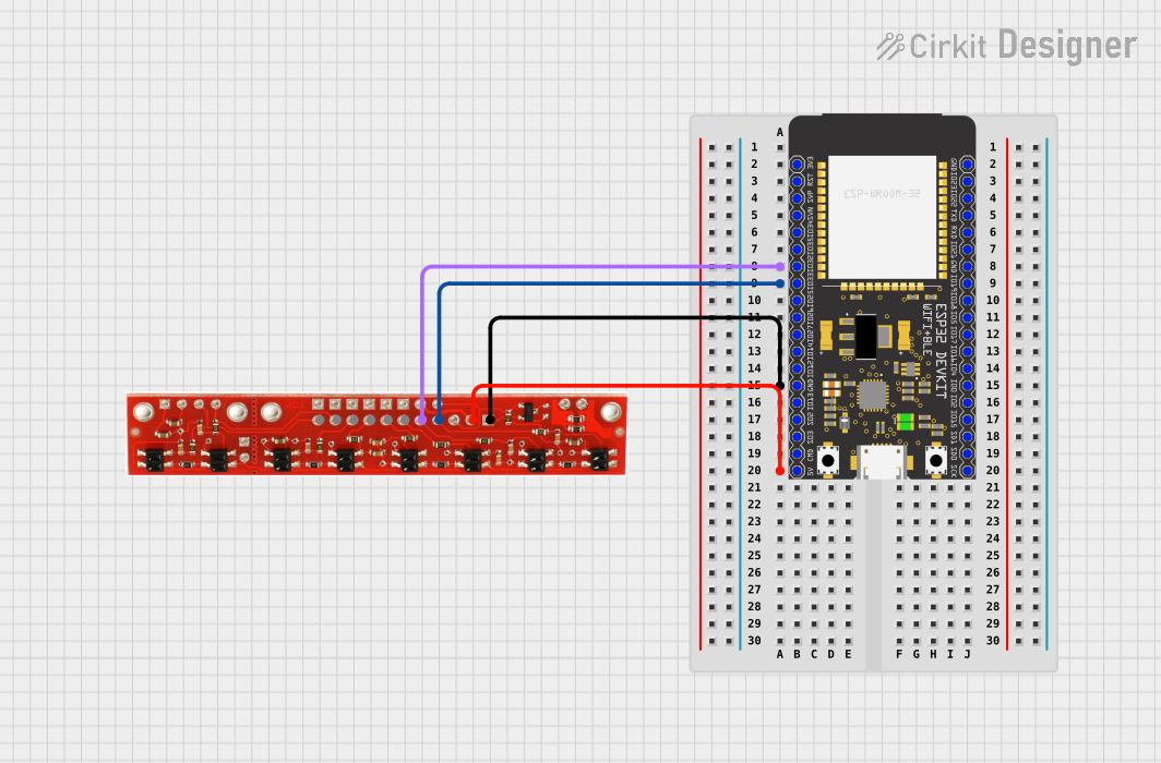
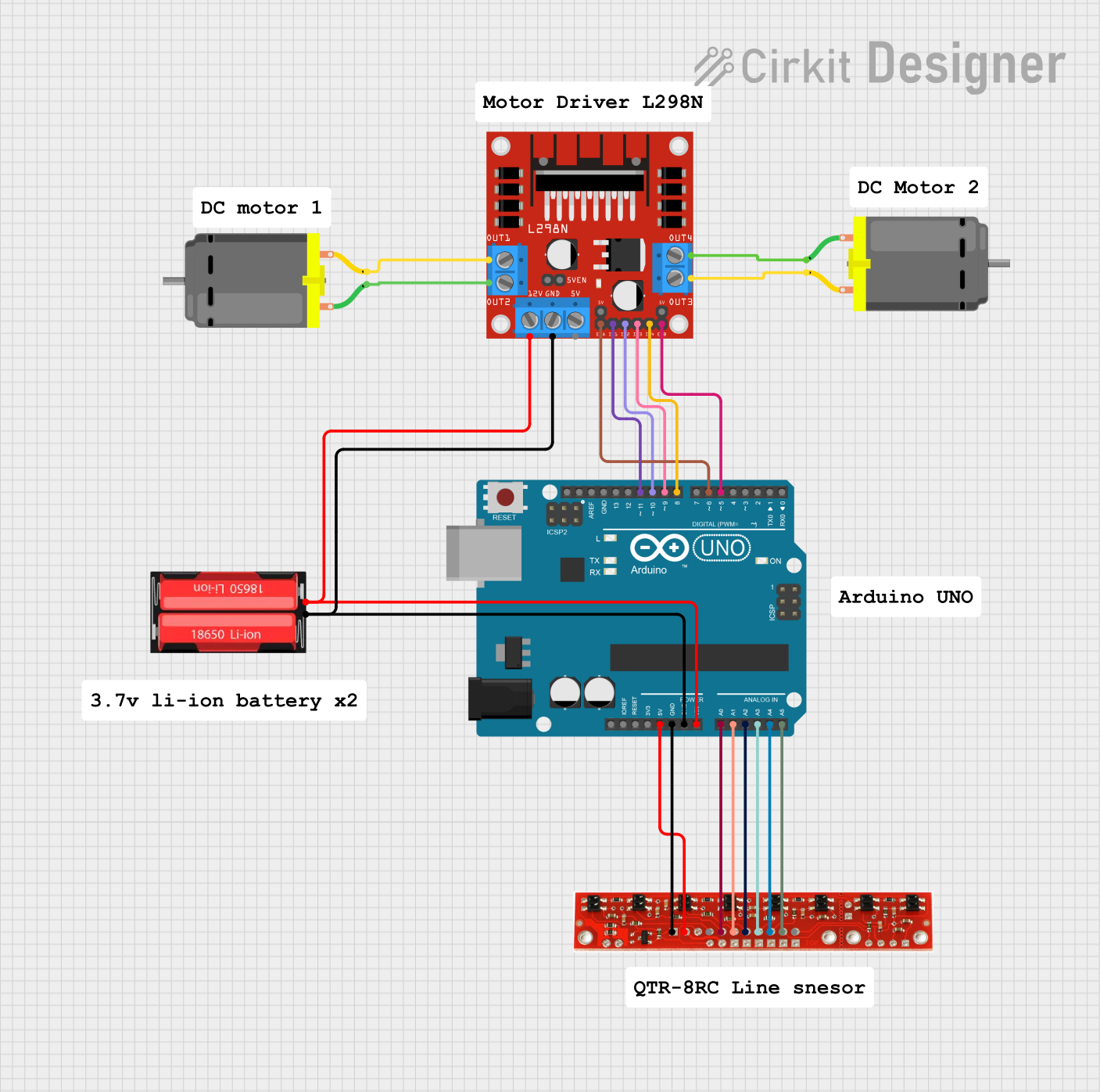
How to Use the Component in a Circuit

  1. Powering the Sensor: Connect the VCC pin to a 3.3V or 5V power supply and the GND pin to the ground.
  2. Connecting Outputs: Connect each sensor output to a digital input pin on your microcontroller.
  3. LEDON Pin (Optional): This pin can be connected to a digital output on your microcontroller if you want to control the IR LEDs programmatically. Otherwise, it can be connected to VCC to keep the LEDs on at all times.

Important Considerations and Best Practices

  • Ensure that the sensor is mounted at the optimal distance from the surface for best performance.
  • Avoid exposing the sensor to direct sunlight or other strong IR sources that may interfere with its operation.
  • Use a microcontroller with enough digital input pins to accommodate all sensor outputs for full functionality.
  • Implement a calibration routine in your software to account for different surface reflectivities.

Example Code for Arduino UNO

// Example code for the Pololu QTR-8RC Reflectance Sensor Array with an Arduino UNO

#include <QTRSensors.h>

// Define the QTR sensor type and Arduino digital pins it's connected to
QTRSensorsRC qtrrc((unsigned char[]) {3, 4, 5, 6, 7, 8, 9, 10}, 8);

// This function reads the sensors and prints the values to the serial monitor
void setup() {
  Serial.begin(9600);
  delay(500);
  qtrrc.calibrate(); // Calibrate the sensor before turning on the IR LEDs
}

void loop() {
  unsigned int sensorValues[8];
  qtrrc.read(sensorValues);
  for (int i = 0; i < 8; i++) {
    Serial.print(sensorValues[i]);
    Serial.print('\t'); // Tab to space out values in the serial monitor
  }
  Serial.println();
  delay(250); // Wait 250ms before reading the sensors again
}

Troubleshooting and FAQs

Common Issues Users Might Face

  • Inconsistent Readings: Ensure that the sensor array is at the correct distance from the surface. Calibrate the sensor for the specific surface you are using.
  • No Readings: Check the power supply and connections to the sensor array. Ensure that the microcontroller pins are configured correctly.
  • Interference from External Light: Shield the sensor from external light sources or adjust the calibration to account for interference.

Solutions and Tips for Troubleshooting

  • Calibration: Perform calibration in the same environmental conditions that the sensor will be used in.
  • Connections: Double-check all connections, especially if the sensor is not responding as expected.
  • Code Debugging: Use serial output to debug and verify that the sensor values are being read correctly.

FAQs

Q: Can I use fewer than eight sensors? A: Yes, you can use any number of sensors between 1 and 8. Simply adjust your code to read the specific sensors you have connected.

Q: How do I control the brightness of the IR LEDs? A: The brightness is fixed, but you can control the LEDs by using the LEDON pin to turn them on or off.

Q: What is the purpose of the LEDON pin? A: The LEDON pin allows you to turn the IR LEDs on or off using a digital output from your microcontroller. This can save power or allow for advanced sensing techniques.

Q: How do I interpret the sensor readings? A: Lower values typically indicate a more reflective surface (such as a white line), while higher values indicate less reflection (such as a black line or no line).

Remember to always refer to the official Pololu QTR-8RC datasheet for the most accurate and detailed information.