Cirkit Designer Logo
Cirkit Designer
Your all-in-one circuit design IDE
Home / 
Component Documentation

How to Use sensor flow water: Examples, Pinouts, and Specs

Image of sensor flow water
Cirkit Designer LogoDesign with sensor flow water in Cirkit Designer

Introduction

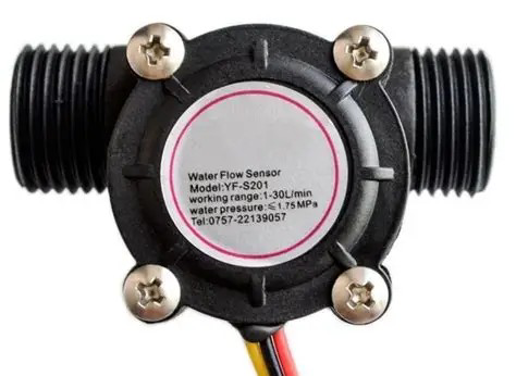
The Arduino Sensor Flow Water is a device designed to measure the flow rate of water in a system. It provides accurate and real-time data, making it ideal for monitoring and controlling water usage in various applications. This sensor is commonly used in irrigation systems, water dispensers, industrial fluid monitoring, and smart home water management systems. Its compact design and compatibility with Arduino microcontrollers make it a versatile and user-friendly component for both hobbyists and professionals.

Explore Projects Built with sensor flow water

Use Cirkit Designer to design, explore, and prototype these projects online. Some projects support real-time simulation. Click "Open Project" to start designing instantly!
Arduino and ESP8266-Based Water Monitoring System with Flow Rate Sensor
Image of Arduino Uno (RP): A project utilizing sensor flow water in a practical application
This circuit monitors water presence and flow rate using a water sensor and a YF-S401 water flow rate sensor, respectively. The Arduino UNO reads the water sensor's analog signal and the flow rate sensor's pulse output, while the ESP8266 is powered but not actively used in this configuration. The Arduino processes and outputs the sensor data via serial communication for monitoring purposes.
Cirkit Designer LogoOpen Project in Cirkit Designer
ESP32 Wi-Fi Connected Water Flow Meter with Battery Power
Image of phil: A project utilizing sensor flow water in a practical application
This circuit features an ESP32 microcontroller connected to a Water Flow Rate Sensor YF-S401 and powered by a 2000mAh battery. The ESP32 reads the water flow data from the sensor, calculates the water volume consumed, and provides this information via a web server over WiFi.
Cirkit Designer LogoOpen Project in Cirkit Designer
Arduino-Based Water Quality Monitoring System with SIM900A and Multiple Sensors
Image of feito: A project utilizing sensor flow water in a practical application
This circuit is a water quality monitoring system that uses an Arduino UNO to collect data from a YF-S201 water flow meter, a turbidity sensor, and a temperature sensor. The collected data is then transmitted via a SIM900A GSM module to a remote server or user through SMS. The system measures water flow rate, temperature, and turbidity, and sends periodic updates.
Cirkit Designer LogoOpen Project in Cirkit Designer
Arduino UNO-Based Water Flow Meter with LCD Display and Flow Rate Sensor
Image of Water Volume Meter: A project utilizing sensor flow water in a practical application
This circuit is a water flow monitoring system using an Arduino UNO, a water flow rate sensor, and a 16x2 I2C LCD. The system measures the flow rate and total volume of water, displaying the data on the LCD, and triggers an alarm if the flow volume exceeds a user-defined limit.
Cirkit Designer LogoOpen Project in Cirkit Designer

Explore Projects Built with sensor flow water

Use Cirkit Designer to design, explore, and prototype these projects online. Some projects support real-time simulation. Click "Open Project" to start designing instantly!
Image of Arduino Uno (RP): A project utilizing sensor flow water in a practical application
Arduino and ESP8266-Based Water Monitoring System with Flow Rate Sensor
This circuit monitors water presence and flow rate using a water sensor and a YF-S401 water flow rate sensor, respectively. The Arduino UNO reads the water sensor's analog signal and the flow rate sensor's pulse output, while the ESP8266 is powered but not actively used in this configuration. The Arduino processes and outputs the sensor data via serial communication for monitoring purposes.
Cirkit Designer LogoOpen Project in Cirkit Designer
Image of phil: A project utilizing sensor flow water in a practical application
ESP32 Wi-Fi Connected Water Flow Meter with Battery Power
This circuit features an ESP32 microcontroller connected to a Water Flow Rate Sensor YF-S401 and powered by a 2000mAh battery. The ESP32 reads the water flow data from the sensor, calculates the water volume consumed, and provides this information via a web server over WiFi.
Cirkit Designer LogoOpen Project in Cirkit Designer
Image of feito: A project utilizing sensor flow water in a practical application
Arduino-Based Water Quality Monitoring System with SIM900A and Multiple Sensors
This circuit is a water quality monitoring system that uses an Arduino UNO to collect data from a YF-S201 water flow meter, a turbidity sensor, and a temperature sensor. The collected data is then transmitted via a SIM900A GSM module to a remote server or user through SMS. The system measures water flow rate, temperature, and turbidity, and sends periodic updates.
Cirkit Designer LogoOpen Project in Cirkit Designer
Image of Water Volume Meter: A project utilizing sensor flow water in a practical application
Arduino UNO-Based Water Flow Meter with LCD Display and Flow Rate Sensor
This circuit is a water flow monitoring system using an Arduino UNO, a water flow rate sensor, and a 16x2 I2C LCD. The system measures the flow rate and total volume of water, displaying the data on the LCD, and triggers an alarm if the flow volume exceeds a user-defined limit.
Cirkit Designer LogoOpen Project in Cirkit Designer

Technical Specifications

  • Manufacturer: Arduino
  • Model: Sensor Flow Water
  • Measurement Range: 1–30 L/min (liters per minute)
  • Operating Voltage: 5V DC
  • Output Signal: Pulse frequency (Hz) proportional to flow rate
  • Accuracy: ±2%
  • Maximum Pressure: 1.75 MPa
  • Operating Temperature: -25°C to 80°C
  • Connector Type: 3-pin (VCC, GND, Signal)

Pin Configuration and Descriptions

Pin Name Description
1 VCC Power supply input (5V DC)
2 GND Ground connection
3 Signal Pulse output signal proportional to flow

Usage Instructions

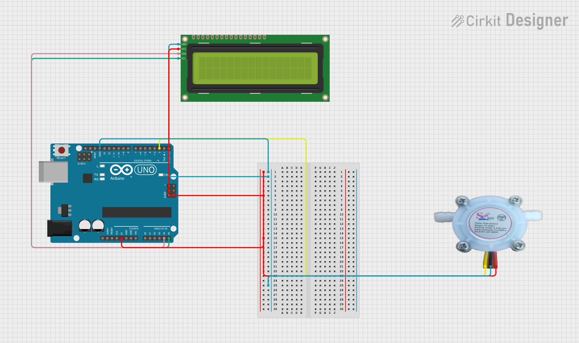
How to Use the Sensor in a Circuit

  1. Wiring the Sensor:

    • Connect the VCC pin of the sensor to the 5V pin on the Arduino.
    • Connect the GND pin of the sensor to the GND pin on the Arduino.
    • Connect the Signal pin of the sensor to a digital input pin on the Arduino (e.g., D2).
  2. Circuit Example:

    • Use a pull-up resistor (10kΩ) on the signal line to ensure stable readings.
    • Ensure the water flow direction matches the arrow on the sensor body.
  3. Arduino Code Example: Below is a sample Arduino sketch to read and calculate the water flow rate:

    // Define the pin connected to the sensor's signal output
    const int flowSensorPin = 2;
    
    // Variables to store pulse count and flow rate
    volatile int pulseCount = 0;
    float flowRate = 0.0;
    unsigned long previousMillis = 0;
    
    // Pulse frequency to flow rate conversion factor (adjust as per sensor specs)
    const float calibrationFactor = 4.5;
    
    void setup() {
      // Initialize serial communication for debugging
      Serial.begin(9600);
    
      // Set the flow sensor pin as input
      pinMode(flowSensorPin, INPUT);
    
      // Attach an interrupt to count pulses from the sensor
      attachInterrupt(digitalPinToInterrupt(flowSensorPin), countPulses, RISING);
    }
    
    void loop() {
      // Calculate flow rate every second
      unsigned long currentMillis = millis();
      if (currentMillis - previousMillis >= 1000) {
        previousMillis = currentMillis;
    
        // Calculate flow rate in liters per minute
        flowRate = (pulseCount / calibrationFactor);
    
        // Print the flow rate to the serial monitor
        Serial.print("Flow Rate: ");
        Serial.print(flowRate);
        Serial.println(" L/min");
    
        // Reset pulse count for the next interval
        pulseCount = 0;
      }
    }
    
    // Interrupt service routine to count pulses
    void countPulses() {
      pulseCount++;
    }
    

Important Considerations and Best Practices

  • Calibration: The calibration factor may vary depending on the specific sensor model. Refer to the datasheet or test the sensor to determine the correct value.
  • Water Quality: Ensure the water is free of debris or particles that could clog the sensor.
  • Orientation: Install the sensor in the correct orientation as indicated by the arrow on the housing.
  • Pressure Limits: Do not exceed the maximum pressure rating of 1.75 MPa to avoid damaging the sensor.

Troubleshooting and FAQs

Common Issues and Solutions

  1. No Output Signal:

    • Check the wiring connections, ensuring VCC, GND, and Signal are properly connected.
    • Verify that the Arduino is powered and the sensor is receiving 5V.
  2. Inaccurate Flow Rate Readings:

    • Ensure the calibration factor in the code matches the sensor's specifications.
    • Check for air bubbles or debris in the water line that may affect flow measurement.
  3. Intermittent Signal:

    • Use a pull-up resistor (10kΩ) on the signal line to stabilize the output.
    • Inspect the sensor for physical damage or wear.

FAQs

Q: Can this sensor measure other liquids besides water?
A: The sensor is designed for water. Using it with other liquids may affect accuracy or damage the sensor. Consult the datasheet for compatibility.

Q: How do I clean the sensor?
A: Disconnect the sensor from the system and rinse it with clean water. Avoid using harsh chemicals or abrasive materials.

Q: Can I use this sensor with a 3.3V microcontroller?
A: The sensor requires a 5V power supply. If using a 3.3V microcontroller, you may need a level shifter for the signal line.

By following this documentation, you can effectively integrate the Arduino Sensor Flow Water into your projects for accurate water flow monitoring and control.