How to Use ULN2003PCB: Examples, Pinouts, and Specs
Introduction
The ULN2003PCB is a printed circuit board (PCB) that integrates the ULN2003 Darlington transistor array, manufactured by JJY. The ULN2003 is a high-voltage, high-current driver IC designed to interface low-power control signals with high-power loads. The PCB simplifies the use of the ULN2003 by providing a pre-assembled, ready-to-use module with convenient pin headers for easy connection.
Explore Projects Built with ULN2003PCB

Explore Projects Built with ULN2003PCB
Common Applications and Use Cases
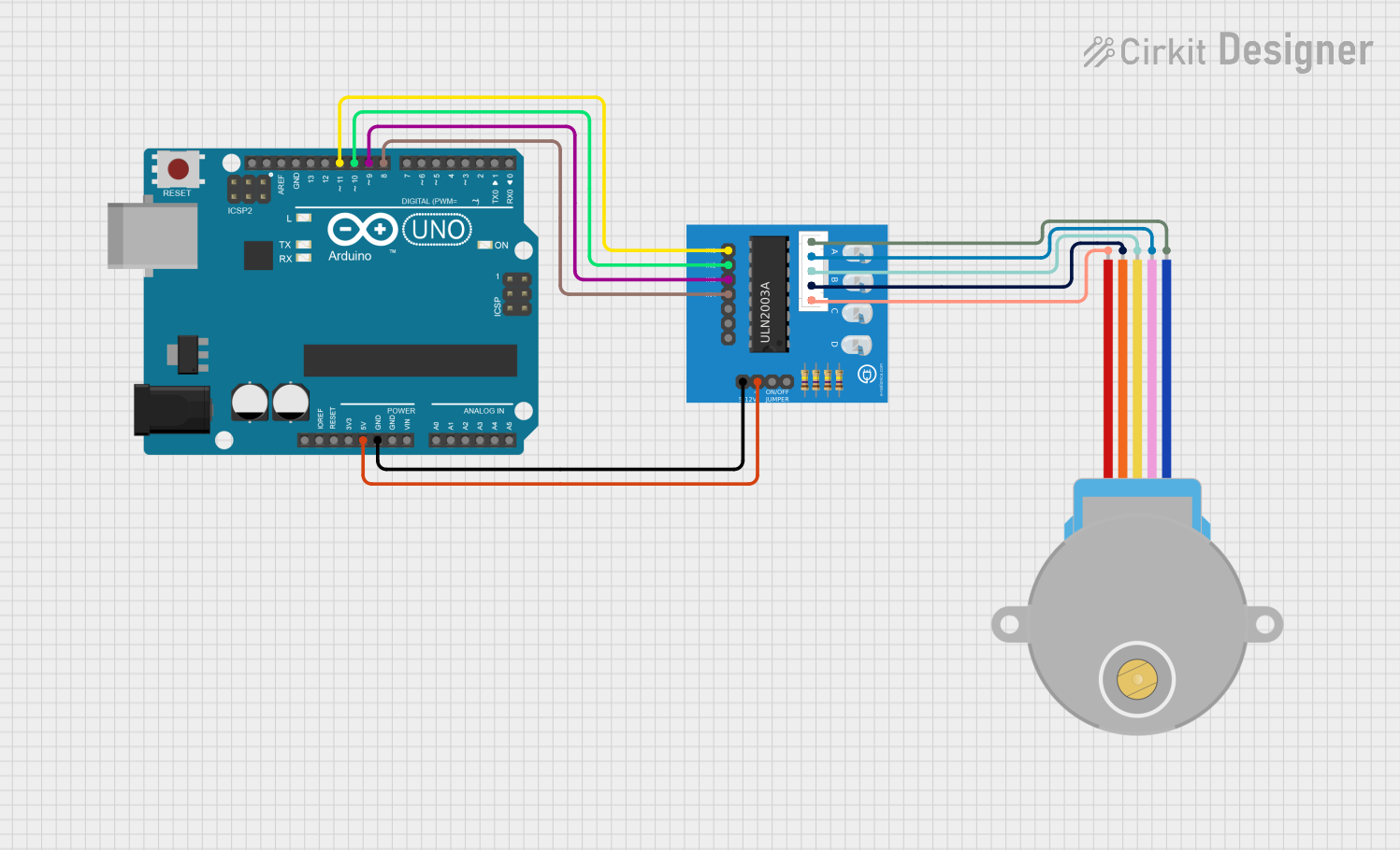
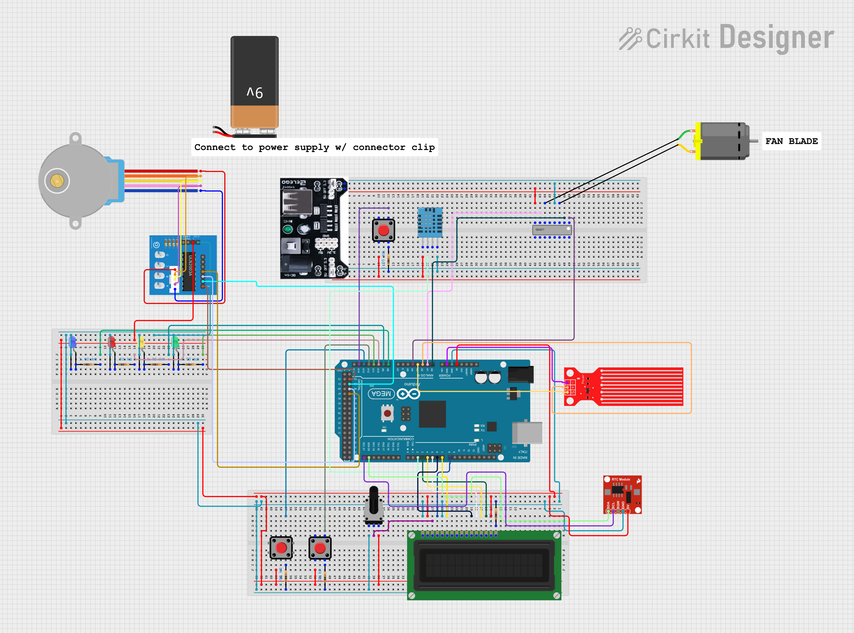
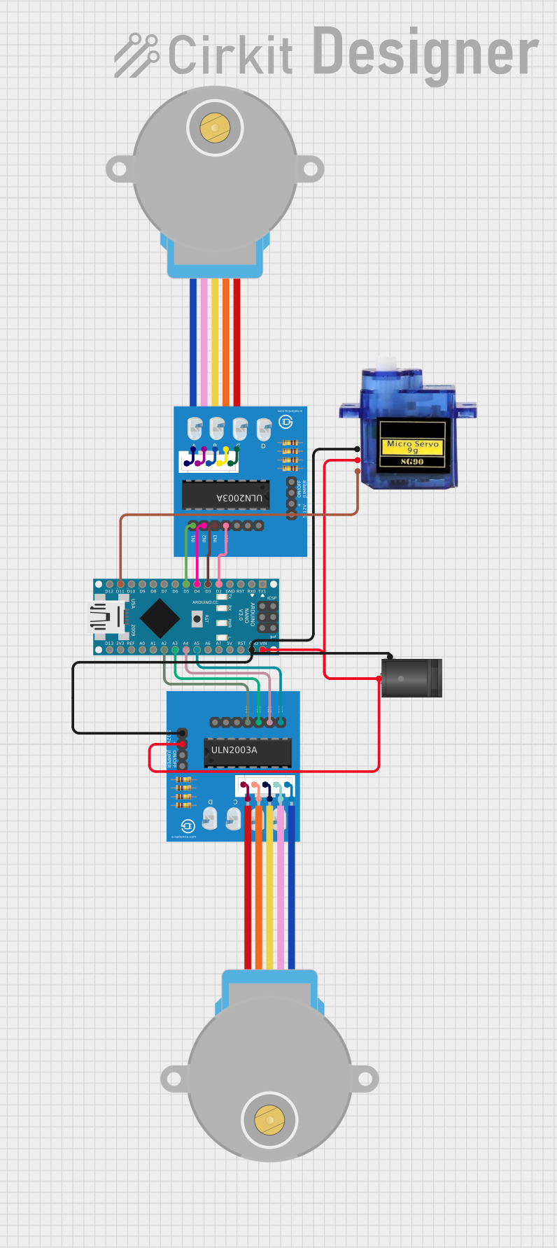
- Driving stepper motors in robotics and automation systems
- Controlling relays for home automation or industrial applications
- Switching high-power LEDs or lamps
- Driving solenoids in vending machines or locking mechanisms
- Interfacing microcontrollers (e.g., Arduino, Raspberry Pi) with high-power devices
Technical Specifications
Key Technical Details
- Manufacturer: JJY
- Part ID: ULN2003PCB
- Input Voltage: 3.3V to 5V (logic level inputs)
- Output Voltage: Up to 50V (load side)
- Output Current: Up to 500mA per channel (maximum total current: 2.5A)
- Number of Channels: 7 (independent Darlington transistor drivers)
- PCB Dimensions: Approximately 40mm x 20mm
- Connector Type: 10-pin header for inputs and outputs
- Integrated Features: Flyback diodes for inductive load protection
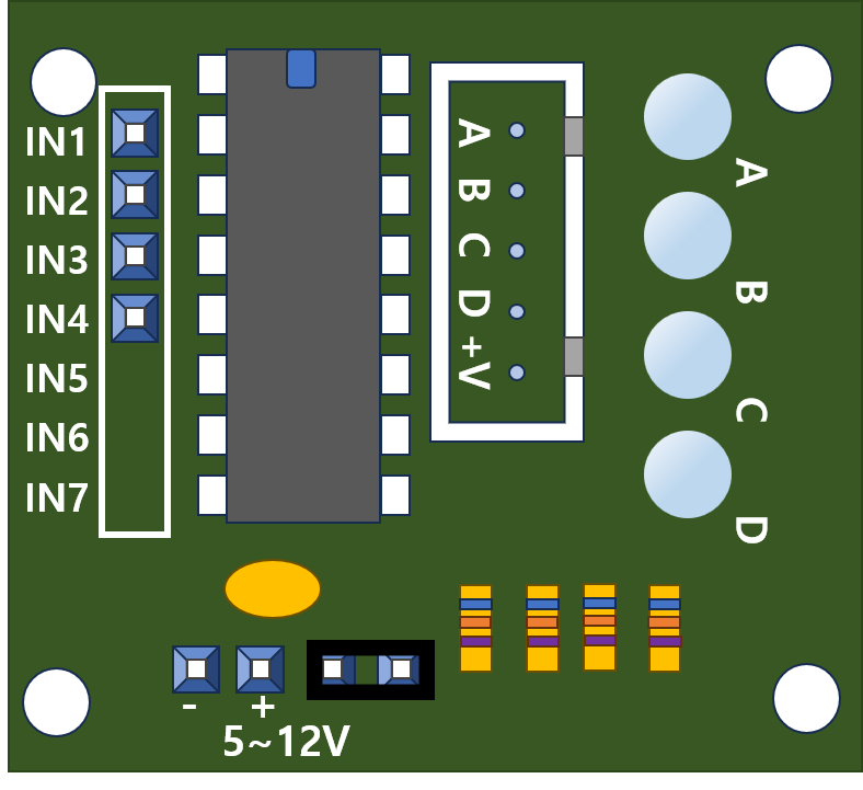
Pin Configuration and Descriptions
The ULN2003PCB has a 10-pin header for easy interfacing. The pin configuration is as follows:
| Pin | Name | Description |
|---|---|---|
| 1 | IN1 | Input signal for Channel 1 (logic level: 3.3V or 5V) |
| 2 | IN2 | Input signal for Channel 2 |
| 3 | IN3 | Input signal for Channel 3 |
| 4 | IN4 | Input signal for Channel 4 |
| 5 | IN5 | Input signal for Channel 5 |
| 6 | IN6 | Input signal for Channel 6 |
| 7 | IN7 | Input signal for Channel 7 |
| 8 | GND | Ground connection for the module |
| 9 | VCC | Power supply for the logic circuit (3.3V or 5V) |
| 10 | COM (Common) | Common cathode for the internal flyback diodes (connect to load power supply) |
Output Terminals
The PCB also includes a 7-pin output terminal block for connecting the load. Each output corresponds to one of the input channels (OUT1 to OUT7).
| Output Pin | Description |
|---|---|
| OUT1 | Output for Channel 1 |
| OUT2 | Output for Channel 2 |
| OUT3 | Output for Channel 3 |
| OUT4 | Output for Channel 4 |
| OUT5 | Output for Channel 5 |
| OUT6 | Output for Channel 6 |
| OUT7 | Output for Channel 7 |
Usage Instructions
How to Use the ULN2003PCB in a Circuit
Power the Module:
- Connect the VCC pin to a 3.3V or 5V power source (depending on your control signal voltage).
- Connect the GND pin to the ground of your power supply.
Connect the Inputs:
- Use the IN1 to IN7 pins to provide control signals from a microcontroller or other logic circuit.
- A HIGH signal (3.3V or 5V) on an input pin will activate the corresponding output channel.
Connect the Outputs:
- Attach your load (e.g., motor, relay, lamp) to the corresponding output pin (OUT1 to OUT7).
- Ensure the load's power supply is connected to the COM pin to enable flyback diode protection.
Verify Connections:
- Double-check all connections to ensure proper wiring and avoid short circuits.
Test the Circuit:
- Power on the system and send control signals to the input pins to activate the desired output channels.
Important Considerations and Best Practices
- Flyback Diode Protection: The ULN2003 includes built-in flyback diodes to protect against voltage spikes from inductive loads. Always connect the COM pin to the positive terminal of the load's power supply.
- Current Limitations: Do not exceed 500mA per channel or 2.5A total current across all channels. Use external transistors or relays for higher current loads.
- Heat Dissipation: For high-current applications, ensure adequate ventilation or heat sinking to prevent overheating.
- Logic Level Compatibility: Ensure the input signals match the logic level of the module (3.3V or 5V).
Example: Using ULN2003PCB with Arduino UNO
Below is an example of how to control a 5V relay using the ULN2003PCB and an Arduino UNO:
// Example: Controlling a relay with ULN2003PCB and Arduino UNO

// Define the input pin connected to ULN2003PCB
const int relayControlPin = 7; // Connect to IN1 on ULN2003PCB

void setup() {
  pinMode(relayControlPin, OUTPUT); // Set the pin as an output
}

void loop() {
  digitalWrite(relayControlPin, HIGH); // Turn on the relay
  delay(1000); // Wait for 1 second
  digitalWrite(relayControlPin, LOW);  // Turn off the relay
  delay(1000); // Wait for 1 second
}
Troubleshooting and FAQs
Common Issues and Solutions
No Output on Load Side:
- Cause: Incorrect wiring or missing power connections.
- Solution: Verify that the VCC, GND, and COM pins are properly connected. Ensure the input signal is HIGH (3.3V or 5V).
Overheating of the Module:
- Cause: Exceeding the current rating of the ULN2003.
- Solution: Reduce the load current or use external relays/transistors for high-power devices.
Inductive Load Not Working Properly:
- Cause: Flyback diode protection not enabled.
- Solution: Ensure the COM pin is connected to the positive terminal of the load's power supply.
Microcontroller Resetting or Malfunctioning:
- Cause: Voltage spikes or noise from the load.
- Solution: Use decoupling capacitors near the microcontroller and ensure proper grounding.
FAQs
Q: Can I use the ULN2003PCB with a 12V motor?
A: Yes, as long as the motor's current does not exceed 500mA per channel. Connect the motor's power supply to the COM pin.Q: Is the ULN2003PCB compatible with 3.3V logic?
A: Yes, the module works with both 3.3V and 5V logic levels.Q: Can I control multiple loads simultaneously?
A: Yes, you can control up to 7 loads, provided the total current does not exceed 2.5A.Q: Do I need external diodes for inductive loads?
A: No, the ULN2003 includes built-in flyback diodes for this purpose.
This concludes the documentation for the ULN2003PCB.