How to Use LILYGO T-SIM7080G S3: Examples, Pinouts, and Specs
Introduction
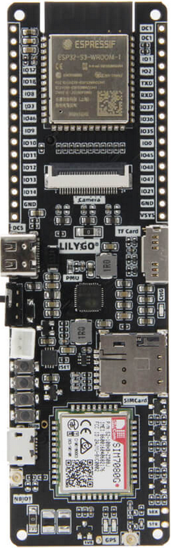
The LILYGO T-SIM7080G S3 is a compact and versatile development board designed for IoT applications. It features the SIM7080G module, which supports LTE Cat-M, NB-IoT, GPS, and GSM communication. This board is ideal for projects requiring wireless connectivity, low-power operation, and location tracking. With its ESP32-S3 microcontroller, the T-SIM7080G S3 offers robust processing power and seamless integration with various sensors and peripherals.
Explore Projects Built with LILYGO T-SIM7080G S3


Explore Projects Built with LILYGO T-SIM7080G S3
Common Applications and Use Cases
- IoT devices for smart homes and industries
- GPS-based location tracking systems
- Remote monitoring and control systems
- Environmental data collection and reporting
- Low-power, wide-area network (LPWAN) applications
Technical Specifications
Key Technical Details
| Parameter | Specification |
|---|---|
| Microcontroller | ESP32-S3 (dual-core, 240 MHz, Wi-Fi, Bluetooth) |
| Cellular Module | SIM7080G (LTE Cat-M, NB-IoT, GPS, GSM) |
| Operating Voltage | 3.3V |
| Input Voltage Range | 5V (via USB-C) |
| Power Consumption | Ultra-low power mode supported |
| Communication Interfaces | UART, I2C, SPI |
| GPS Support | Yes (with integrated SIM7080G GPS functionality) |
| Antenna Ports | LTE and GPS antenna connectors |
| Dimensions | Compact form factor |
Pin Configuration and Descriptions
| Pin Name | Description |
|---|---|
| 3V3 | 3.3V power output |
| GND | Ground |
| TXD | UART transmit pin (connected to SIM7080G) |
| RXD | UART receive pin (connected to SIM7080G) |
| GPIO | General-purpose input/output pins |
| I2C_SCL | I2C clock line |
| I2C_SDA | I2C data line |
| SPI_MOSI | SPI master-out, slave-in |
| SPI_MISO | SPI master-in, slave-out |
| SPI_SCK | SPI clock |
| SIM_PWR | Power control for the SIM7080G module |
| RESET | Reset pin for the ESP32-S3 |
Usage Instructions
How to Use the Component in a Circuit
- Powering the Board: Connect the T-SIM7080G S3 to a 5V power source via the USB-C port. Ensure the power supply is stable to avoid damage.
- Connecting Antennas: Attach the LTE and GPS antennas to their respective connectors for optimal signal reception.
- Programming the ESP32-S3: Use the Arduino IDE or ESP-IDF to program the ESP32-S3. Install the necessary board definitions and libraries for the ESP32-S3 and SIM7080G.
- Interfacing with Peripherals: Use the GPIO, I2C, or SPI pins to connect sensors, actuators, or other peripherals.
- Establishing Cellular Connectivity: Insert a compatible SIM card into the SIM7080G slot. Configure the APN settings in your code to enable LTE or NB-IoT communication.
Important Considerations and Best Practices
- Ensure the SIM card supports LTE Cat-M or NB-IoT for optimal performance.
- Use proper decoupling capacitors to minimize noise and ensure stable operation.
- Avoid placing the board near high-frequency noise sources to maintain GPS accuracy.
- When using GPS, ensure the antenna has a clear view of the sky for better signal reception.
- Monitor power consumption in low-power applications and utilize the ultra-low power modes of the ESP32-S3 and SIM7080G.
Example Code for Arduino UNO
Below is an example of how to send an HTTP GET request using the SIM7080G module:
#include <SoftwareSerial.h>

// Define RX and TX pins for communication with SIM7080G
SoftwareSerial sim7080(10, 11); // RX = 10, TX = 11

void setup() {
  Serial.begin(115200); // Initialize Serial Monitor
  sim7080.begin(9600);  // Initialize SIM7080G communication

  // Send AT command to check module response
  sim7080.println("AT");
  delay(1000);
  while (sim7080.available()) {
    Serial.write(sim7080.read()); // Print response to Serial Monitor
  }

  // Configure APN for your network provider
  sim7080.println("AT+CGDCONT=1,\"IP\",\"your_apn_here\"");
  delay(1000);
  while (sim7080.available()) {
    Serial.write(sim7080.read());
  }

  // Connect to the network
  sim7080.println("AT+CGATT=1");
  delay(1000);
  while (sim7080.available()) {
    Serial.write(sim7080.read());
  }

  // Send HTTP GET request
  sim7080.println("AT+HTTPINIT");
  delay(1000);
  sim7080.println("AT+HTTPPARA=\"URL\",\"http://example.com\"");
  delay(1000);
  sim7080.println("AT+HTTPACTION=0");
  delay(5000); // Wait for response
  while (sim7080.available()) {
    Serial.write(sim7080.read());
  }
}

void loop() {
  // Keep the loop empty for this example
}
Note: Replace your_apn_here with the APN provided by your SIM card provider. Ensure the RX and TX pins are correctly connected to the SIM7080G module.
Troubleshooting and FAQs
Common Issues and Solutions
No Response from SIM7080G:
- Ensure the module is powered on and the SIM card is properly inserted.
- Check the RX and TX connections between the microcontroller and the SIM7080G.
Unable to Connect to Network:
- Verify the APN settings in your code.
- Ensure the SIM card has an active data plan and supports LTE Cat-M or NB-IoT.
GPS Not Working:
- Ensure the GPS antenna is connected and has a clear view of the sky.
- Wait for a few minutes to allow the module to acquire satellite signals.
High Power Consumption:
- Use the ultra-low power modes of the ESP32-S3 and SIM7080G when the device is idle.
- Disconnect unused peripherals to reduce power draw.
FAQs
Can I use this board with other microcontrollers? Yes, the SIM7080G module can be interfaced with other microcontrollers via UART, I2C, or SPI.
What is the maximum data rate supported by the SIM7080G? The SIM7080G supports LTE Cat-M and NB-IoT with data rates up to 375 kbps.
Does the board support 5G networks? No, the SIM7080G module supports LTE Cat-M, NB-IoT, and GSM networks only.
Can I use this board for battery-powered applications? Yes, the board is designed for low-power operation, making it suitable for battery-powered IoT devices.