Cirkit Designer Logo
Cirkit Designer
Your all-in-one circuit design IDE
Home / 
Component Documentation

How to Use stm32 bluepill: Examples, Pinouts, and Specs

Image of stm32 bluepill
Cirkit Designer LogoDesign with stm32 bluepill in Cirkit Designer

Introduction

The STM32 Blue Pill is a low-cost development board manufactured by Bluepill, featuring the STM32F103C8T6 microcontroller. It is based on the ARM Cortex-M3 architecture and is widely used for prototyping, embedded systems, and IoT projects. Its compact size, affordability, and versatile I/O options make it a popular choice among hobbyists and professionals alike.

Explore Projects Built with stm32 bluepill

Use Cirkit Designer to design, explore, and prototype these projects online. Some projects support real-time simulation. Click "Open Project" to start designing instantly!
STM32F4 and ENC28J60 Ethernet-Enabled Microcontroller Project
Image of youssef: A project utilizing stm32 bluepill in a practical application
This circuit integrates an STM32F4 BlackPill microcontroller with an ENC28J60 Ethernet Board to enable Ethernet connectivity. The microcontroller communicates with the Ethernet board via SPI, with connections for power, ground, and SPI signals (SI, SO, SCK, and CS). The provided code is a basic template for further development.
Cirkit Designer LogoOpen Project in Cirkit Designer
STM32F103C8T6 Bluetooth-Controlled Arcade Joystick Interface
Image of RC카 조이스틱: A project utilizing stm32 bluepill in a practical application
This circuit features an STM32F103C8T6 microcontroller interfaced with a Bluetooth HC-06 module for wireless communication and an Adafruit Arcade Joystick for user input. The microcontroller's pins B0 and B10 are connected to the TXD and RXD pins of the Bluetooth module, enabling serial communication, while pins B14 and B15 interface with the joystick's directional controls. The circuit is powered by a battery, with power distribution managed through the microcontroller's 3.3V pin and common ground connections.
Cirkit Designer LogoOpen Project in Cirkit Designer
ESP32-WROOM Bluetooth-Enabled Battery-Powered Button Interface with OLED Display
Image of Bluetooth Page Turner: A project utilizing stm32 bluepill in a practical application
This circuit is a Bluetooth-enabled battery monitoring and control system using an ESP32 microcontroller. It features multiple push buttons for user input, an OLED display for showing battery voltage and percentage, and a blue LED for status indication. The system also includes a LiPo charger/booster and a USB Type C power delivery module for power management.
Cirkit Designer LogoOpen Project in Cirkit Designer
STM32F4-Based Multi-Sensor GPS Tracking System
Image of Phase 1 fc: A project utilizing stm32 bluepill in a practical application
This circuit integrates an STM32F4 microcontroller with a GPS module (NEO 6M), an accelerometer and gyroscope (MPU-6050), a barometric pressure sensor (BMP280), and a compass (HMC5883L). The microcontroller communicates with the sensors via I2C and the GPS module via UART, enabling it to gather and process environmental and positional data.
Cirkit Designer LogoOpen Project in Cirkit Designer

Explore Projects Built with stm32 bluepill

Use Cirkit Designer to design, explore, and prototype these projects online. Some projects support real-time simulation. Click "Open Project" to start designing instantly!
Image of youssef: A project utilizing stm32 bluepill in a practical application
STM32F4 and ENC28J60 Ethernet-Enabled Microcontroller Project
This circuit integrates an STM32F4 BlackPill microcontroller with an ENC28J60 Ethernet Board to enable Ethernet connectivity. The microcontroller communicates with the Ethernet board via SPI, with connections for power, ground, and SPI signals (SI, SO, SCK, and CS). The provided code is a basic template for further development.
Cirkit Designer LogoOpen Project in Cirkit Designer
Image of RC카 조이스틱: A project utilizing stm32 bluepill in a practical application
STM32F103C8T6 Bluetooth-Controlled Arcade Joystick Interface
This circuit features an STM32F103C8T6 microcontroller interfaced with a Bluetooth HC-06 module for wireless communication and an Adafruit Arcade Joystick for user input. The microcontroller's pins B0 and B10 are connected to the TXD and RXD pins of the Bluetooth module, enabling serial communication, while pins B14 and B15 interface with the joystick's directional controls. The circuit is powered by a battery, with power distribution managed through the microcontroller's 3.3V pin and common ground connections.
Cirkit Designer LogoOpen Project in Cirkit Designer
Image of Bluetooth Page Turner: A project utilizing stm32 bluepill in a practical application
ESP32-WROOM Bluetooth-Enabled Battery-Powered Button Interface with OLED Display
This circuit is a Bluetooth-enabled battery monitoring and control system using an ESP32 microcontroller. It features multiple push buttons for user input, an OLED display for showing battery voltage and percentage, and a blue LED for status indication. The system also includes a LiPo charger/booster and a USB Type C power delivery module for power management.
Cirkit Designer LogoOpen Project in Cirkit Designer
Image of Phase 1 fc: A project utilizing stm32 bluepill in a practical application
STM32F4-Based Multi-Sensor GPS Tracking System
This circuit integrates an STM32F4 microcontroller with a GPS module (NEO 6M), an accelerometer and gyroscope (MPU-6050), a barometric pressure sensor (BMP280), and a compass (HMC5883L). The microcontroller communicates with the sensors via I2C and the GPS module via UART, enabling it to gather and process environmental and positional data.
Cirkit Designer LogoOpen Project in Cirkit Designer

Common Applications and Use Cases

  • Robotics and motor control
  • IoT devices and home automation
  • Data acquisition and sensor interfacing
  • Signal processing and real-time applications
  • Educational projects and microcontroller learning

Technical Specifications

The STM32 Blue Pill is built around the STM32F103C8T6 microcontroller, offering the following key specifications:

Key Technical Details

  • Microcontroller: STM32F103C8T6 (ARM Cortex-M3 core)
  • Clock Speed: 72 MHz
  • Flash Memory: 64 KB
  • SRAM: 20 KB
  • Operating Voltage: 3.3V (5V tolerant I/O pins)
  • I/O Pins: 37 GPIO pins
  • Communication Interfaces:
    • 2x I2C
    • 3x USART
    • 2x SPI
    • 1x CAN
  • ADC: 10 channels, 12-bit resolution
  • PWM Outputs: 15 channels
  • Timers: 7 (4 general-purpose, 2 advanced, 1 system)
  • USB: Full-speed USB 2.0
  • Power Supply: 5V via USB or external power source
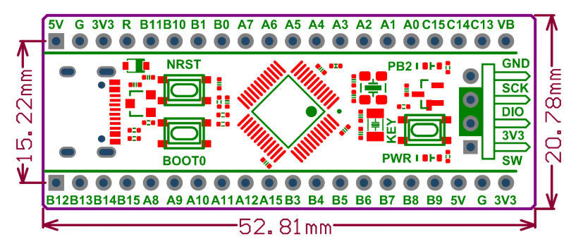
  • Dimensions: 53 mm x 22 mm

Pin Configuration and Descriptions

The STM32 Blue Pill has a 40-pin layout. Below is the pin configuration:

Pin Label Description
1 GND Ground
2 3.3V 3.3V Power Output
3 5V 5V Power Input
4-37 GPIOx General Purpose I/O (x = A0-A15, B0-B15)
38 NRST Reset Pin
39 BOOT0 Boot Mode Selection
40 USB+ USB Data Positive
41 USB- USB Data Negative

For a detailed pinout diagram, refer to the STM32 Blue Pill datasheet.

Usage Instructions

How to Use the STM32 Blue Pill in a Circuit

  1. Powering the Board:

    • Connect the board to a 5V power source via the USB port or the 5V pin.
    • Ensure the BOOT0 pin is set to 0 (GND) for normal operation.
  2. Programming the Board:

    • Use an ST-Link programmer or a USB-to-serial adapter to upload code.
    • Install the STM32CubeIDE or Arduino IDE with the STM32 core for development.
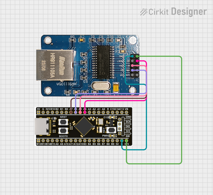
  3. Connecting Peripherals:

    • Use GPIO pins for digital I/O operations.
    • Connect sensors or modules to the I2C, SPI, or USART interfaces as needed.
  4. Flashing Code:

    • For Arduino IDE:
      • Install the STM32 board package via the Board Manager.
      • Select "Generic STM32F103C8" as the board.
      • Upload the code using the "Upload" button.

Important Considerations and Best Practices

  • Voltage Levels: Although the board operates at 3.3V, its I/O pins are 5V tolerant. Avoid exceeding 5V on any pin.
  • Boot Modes: Use the BOOT0 pin to switch between normal operation and bootloader mode for firmware updates.
  • External Pull-Up Resistors: For I2C communication, ensure pull-up resistors (typically 4.7kΩ) are connected to the SDA and SCL lines.
  • Decoupling Capacitors: Add decoupling capacitors (e.g., 0.1 µF) near power pins for stable operation.

Example Code for Arduino IDE

Below is an example of blinking an LED connected to pin PA5:

// Blink an LED on STM32 Blue Pill (PA5)

// Define the LED pin
#define LED_PIN PA5

void setup() {
  pinMode(LED_PIN, OUTPUT); // Set PA5 as an output pin
}

void loop() {
  digitalWrite(LED_PIN, HIGH); // Turn the LED on
  delay(500);                  // Wait for 500 milliseconds
  digitalWrite(LED_PIN, LOW);  // Turn the LED off
  delay(500);                  // Wait for 500 milliseconds
}

Troubleshooting and FAQs

Common Issues and Solutions

  1. Board Not Detected by PC:

    • Ensure the USB cable is functional and supports data transfer.
    • Check if the BOOT0 pin is set to 0 for normal operation.
  2. Code Upload Fails:

    • Verify the correct board and port are selected in the IDE.
    • If using an ST-Link, ensure the drivers are installed and the connection is secure.
  3. Unstable Operation:

    • Check the power supply for sufficient current (at least 500 mA).
    • Add decoupling capacitors near the power pins.
  4. I2C or SPI Communication Issues:

    • Confirm the correct pin connections and use appropriate pull-up resistors for I2C.
    • Verify the clock speed and settings in the code.

FAQs

Q: Can I use the STM32 Blue Pill with the Arduino IDE?
A: Yes, the STM32 Blue Pill is compatible with the Arduino IDE. Install the STM32 core via the Board Manager to get started.

Q: How do I reset the board?
A: Press the onboard reset button or toggle the NRST pin to reset the board.

Q: What is the maximum current output of the GPIO pins?
A: Each GPIO pin can source or sink up to 20 mA, with a total limit of 150 mA for all pins combined.

Q: Can I power the board with 3.3V directly?
A: Yes, you can power the board via the 3.3V pin, but ensure the voltage is stable and regulated.

This concludes the documentation for the STM32 Blue Pill. For further details, refer to the official datasheet and user manual.