Cirkit Designer Logo
Cirkit Designer
Your all-in-one circuit design IDE
Home / 
Component Documentation

How to Use Adafruit Metro with Headers: Examples, Pinouts, and Specs

Image of Adafruit Metro with Headers
Cirkit Designer LogoDesign with Adafruit Metro with Headers in Cirkit Designer

Introduction

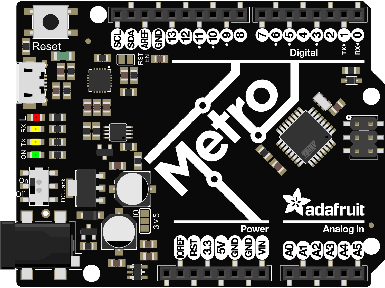
The Adafruit Metro with Headers is a versatile and user-friendly development board based on the ATmega328P microcontroller, which is the same microcontroller used in the popular Arduino UNO. This board is designed for hobbyists, educators, and professionals who need a reliable platform for electronics projects. With pre-soldered headers, the Metro provides an easy way to connect a wide range of components and peripherals without the need for soldering, making it ideal for prototyping and quick experimentation.

Explore Projects Built with Adafruit Metro with Headers

Use Cirkit Designer to design, explore, and prototype these projects online. Some projects support real-time simulation. Click "Open Project" to start designing instantly!
Arduino-Based Temperature Monitoring System with RGB LED Feedback and I2C LCD Display
Image of wemos custom shield: A project utilizing Adafruit Metro with Headers in a practical application
This circuit features an Adafruit Proto Shield R3 configured with a DS18B20 temperature sensor, a WS2812 RGB LED matrix, and an LCD I2C display. The microcontroller on the Proto Shield reads the temperature from the DS18B20 sensor and displays it on the LCD. It also controls the LED matrix to show random colors and indicates temperature status with onboard LEDs.
Cirkit Designer LogoOpen Project in Cirkit Designer
Raspberry Pi 4B-Based Multi-Sensor Interface Hub with GPS and GSM
Image of Rocket: A project utilizing Adafruit Metro with Headers in a practical application
This circuit features a Raspberry Pi 4B interfaced with an IMX296 color global shutter camera, a Neo 6M GPS module, an Adafruit BMP388 barometric pressure sensor, an MPU-6050 accelerometer/gyroscope, and a Sim800l GSM module for cellular connectivity. Power management is handled by an MT3608 boost converter, which steps up the voltage from a Lipo battery, with a resettable fuse PTC and a 1N4007 diode for protection. The Adafruit Perma-Proto HAT is used for organizing connections and interfacing the sensors and modules with the Raspberry Pi via I2C and GPIO pins.
Cirkit Designer LogoOpen Project in Cirkit Designer
Arduino Mega 2560-Based Multi-Sensor Weather Station with TFT Display and IR Control
Image of aqua2: A project utilizing Adafruit Metro with Headers in a practical application
This circuit uses an Arduino Mega 2560 to read temperature data from multiple DS18B20 sensors, display the data on an ILI9341 TFT display, and maintain time using an Adafruit DS1307 RTC module. It also receives IR signals using a VS1838B IR receiver and includes an Adafruit MS8607 PHT sensor for additional environmental monitoring.
Cirkit Designer LogoOpen Project in Cirkit Designer
Multi-Sensor Health Monitoring System with Adafruit Feather M0 Adalogger
Image of health tracker: A project utilizing Adafruit Metro with Headers in a practical application
This circuit is designed to interface multiple sensors with an Adafruit Feather M0 Adalogger microcontroller for data logging purposes. The sensors include a MAX30205 temperature sensor, a body dehydration sensor, a MAX30102 pulse oximeter, an Adafruit LSM6DSOX 6-axis accelerometer and gyroscope, and an Adafruit BME680 environmental sensor. All sensors are connected to the microcontroller via an I2C bus, sharing the SDA and SCL lines for communication.
Cirkit Designer LogoOpen Project in Cirkit Designer

Explore Projects Built with Adafruit Metro with Headers

Use Cirkit Designer to design, explore, and prototype these projects online. Some projects support real-time simulation. Click "Open Project" to start designing instantly!
Image of wemos custom shield: A project utilizing Adafruit Metro with Headers in a practical application
Arduino-Based Temperature Monitoring System with RGB LED Feedback and I2C LCD Display
This circuit features an Adafruit Proto Shield R3 configured with a DS18B20 temperature sensor, a WS2812 RGB LED matrix, and an LCD I2C display. The microcontroller on the Proto Shield reads the temperature from the DS18B20 sensor and displays it on the LCD. It also controls the LED matrix to show random colors and indicates temperature status with onboard LEDs.
Cirkit Designer LogoOpen Project in Cirkit Designer
Image of Rocket: A project utilizing Adafruit Metro with Headers in a practical application
Raspberry Pi 4B-Based Multi-Sensor Interface Hub with GPS and GSM
This circuit features a Raspberry Pi 4B interfaced with an IMX296 color global shutter camera, a Neo 6M GPS module, an Adafruit BMP388 barometric pressure sensor, an MPU-6050 accelerometer/gyroscope, and a Sim800l GSM module for cellular connectivity. Power management is handled by an MT3608 boost converter, which steps up the voltage from a Lipo battery, with a resettable fuse PTC and a 1N4007 diode for protection. The Adafruit Perma-Proto HAT is used for organizing connections and interfacing the sensors and modules with the Raspberry Pi via I2C and GPIO pins.
Cirkit Designer LogoOpen Project in Cirkit Designer
Image of aqua2: A project utilizing Adafruit Metro with Headers in a practical application
Arduino Mega 2560-Based Multi-Sensor Weather Station with TFT Display and IR Control
This circuit uses an Arduino Mega 2560 to read temperature data from multiple DS18B20 sensors, display the data on an ILI9341 TFT display, and maintain time using an Adafruit DS1307 RTC module. It also receives IR signals using a VS1838B IR receiver and includes an Adafruit MS8607 PHT sensor for additional environmental monitoring.
Cirkit Designer LogoOpen Project in Cirkit Designer
Image of health tracker: A project utilizing Adafruit Metro with Headers in a practical application
Multi-Sensor Health Monitoring System with Adafruit Feather M0 Adalogger
This circuit is designed to interface multiple sensors with an Adafruit Feather M0 Adalogger microcontroller for data logging purposes. The sensors include a MAX30205 temperature sensor, a body dehydration sensor, a MAX30102 pulse oximeter, an Adafruit LSM6DSOX 6-axis accelerometer and gyroscope, and an Adafruit BME680 environmental sensor. All sensors are connected to the microcontroller via an I2C bus, sharing the SDA and SCL lines for communication.
Cirkit Designer LogoOpen Project in Cirkit Designer

Common Applications and Use Cases

  • Educational projects and learning the basics of electronics and programming
  • Prototyping electronic circuits and devices
  • DIY home automation systems
  • Robotics and control systems
  • Wearable electronics
  • Internet of Things (IoT) devices

Technical Specifications

Key Technical Details

  • Microcontroller: ATmega328P
  • Operating Voltage: 5V
  • Input Voltage (recommended): 7-12V
  • Input Voltage (limits): 6-20V
  • Digital I/O Pins: 20 (6 of which provide PWM output)
  • Analog Input Pins: 6
  • DC Current per I/O Pin: 20 mA
  • DC Current for 3.3V Pin: 50 mA
  • Flash Memory: 32 KB (ATmega328P) of which 0.5 KB used by bootloader
  • SRAM: 2 KB (ATmega328P)
  • EEPROM: 1 KB (ATmega328P)
  • Clock Speed: 16 MHz
  • LED_BUILTIN: Pin 13

Pin Configuration and Descriptions

Pin Number Function Description
1 RESET Used to reset the microcontroller
2-13 Digital I/O Digital input/output pins, PWM on 3, 5, 6, 9, 10, 11
14-19 Analog Input Analog input pins A0-A5
20, 21 SDA, SCL I2C data and clock lines
22, 23 RX, TX UART receive and transmit
24 5V Regulated power supply for the board and components
25 3.3V Regulated power supply for 3.3V components
26 GND Ground
27 AREF Analog reference voltage for the ADC
28 VIN Input voltage to the board

Usage Instructions

How to Use the Component in a Circuit

  1. Powering the Board: Connect a 7-12V power supply to the VIN and GND pins, or plug in a USB cable to the board's USB port to power it via USB.

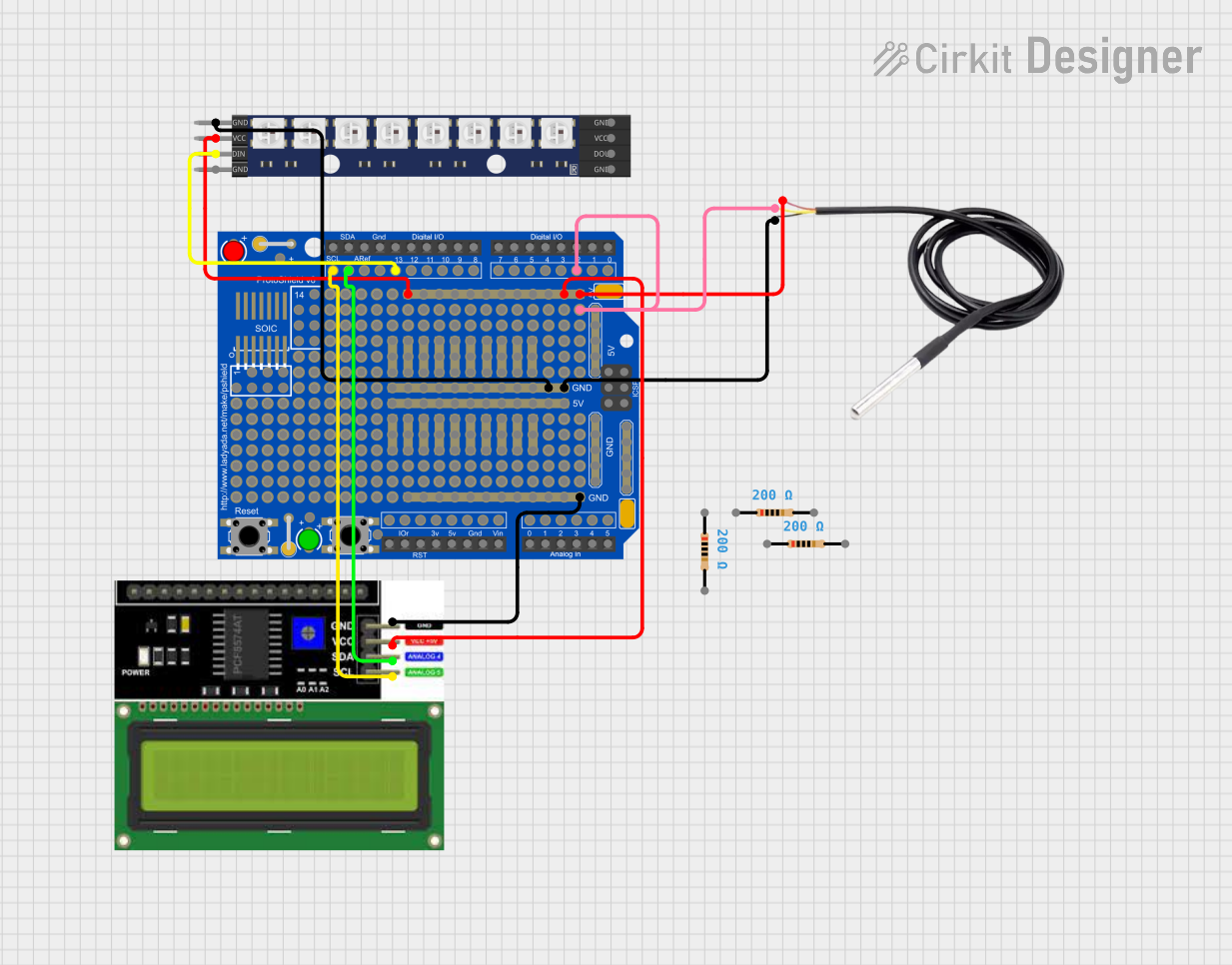
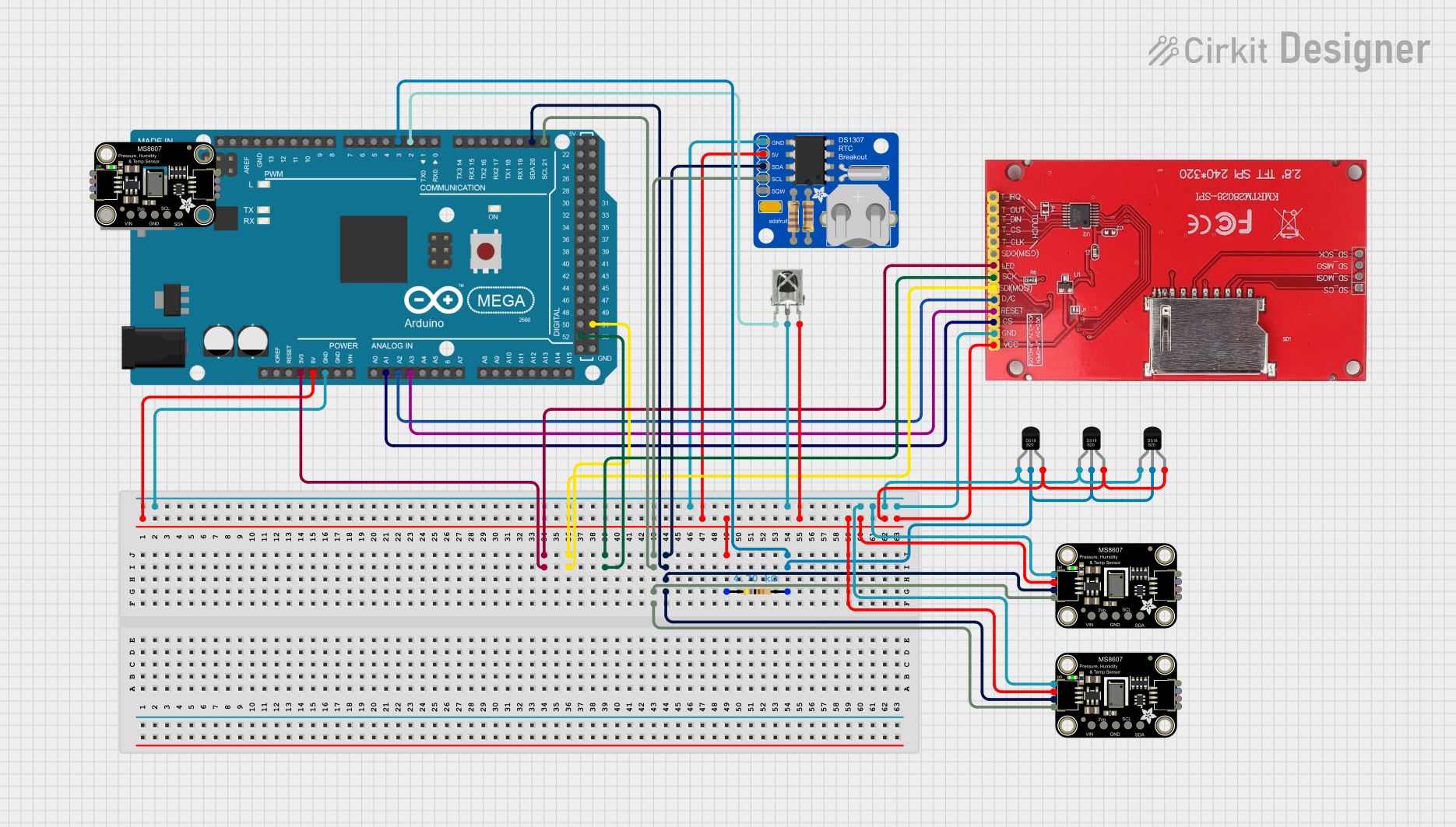
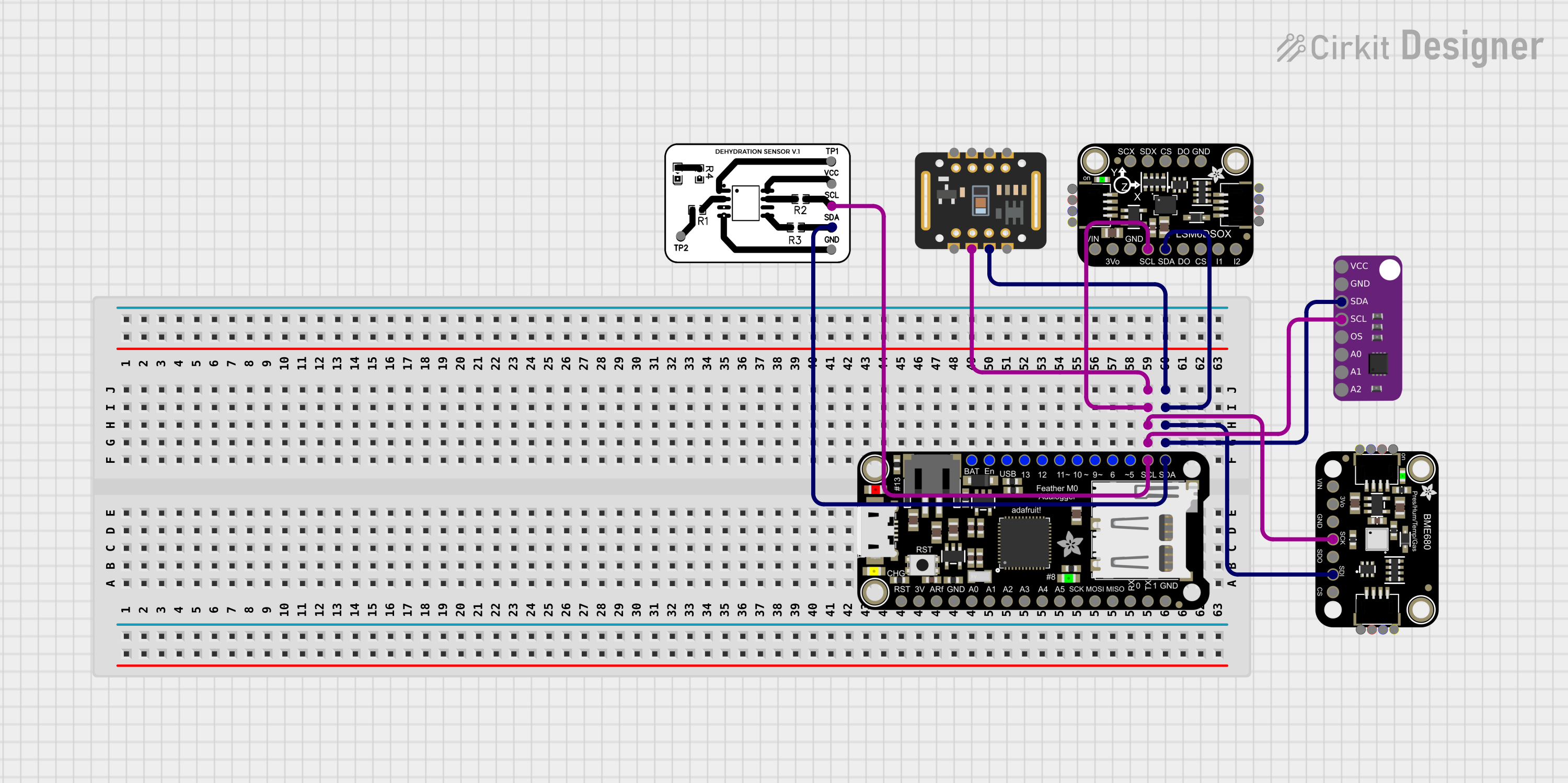
  2. Connecting Peripherals: Use the digital and analog pins to connect sensors, actuators, displays, and other components. Ensure that the peripherals are compatible with the board's operating voltage.

  3. Programming the Board: The Adafruit Metro with Headers can be programmed using the Arduino IDE. Select "Arduino UNO" as the board type, as the Metro is pin-compatible with the UNO.

Important Considerations and Best Practices

  • Always disconnect the board from power sources before making or altering connections.
  • Observe proper polarity for power connections to avoid damaging the board.
  • Do not exceed the recommended voltage and current ratings for the pins.
  • Use external power sources when connecting components that draw more current than the board can provide.

Troubleshooting and FAQs

Common Issues Users Might Face

  • Board not recognized by computer: Ensure the USB cable is properly connected and the correct drivers are installed.
  • Incorrect or erratic behavior: Double-check connections and ensure the code is uploaded correctly. Also, verify that the power supply is stable and within the recommended range.

Solutions and Tips for Troubleshooting

  • If the board is not recognized, try a different USB cable or port, and ensure the Arduino IDE has the correct board and port selected.
  • For erratic behavior, simplify the circuit to the minimum configuration and gradually add components to isolate the issue.

FAQs

Q: Can I use shields designed for the Arduino UNO with the Adafruit Metro? A: Yes, the Metro is designed to be pin-compatible with the Arduino UNO, so most shields should work.

Q: What should I do if I accidentally connect a higher voltage to the I/O pins? A: Disconnect the power immediately. The board may be damaged, but sometimes it can survive if the exposure to the higher voltage was brief.

Q: How do I reset the board? A: You can press the reset button on the board or momentarily connect the RESET pin to GND.

Example Code for Arduino UNO

Here is a simple example of blinking the onboard LED using the Adafruit Metro with Headers:

// Pin 13 has an LED connected on most Arduino boards.
int led = 13;

// The setup routine runs once when you press reset:
void setup() {                
  // Initialize the digital pin as an output.
  pinMode(led, OUTPUT);     
}

// The loop routine runs over and over again forever:
void loop() {
  digitalWrite(led, HIGH);   // Turn the LED on (HIGH is the voltage level)
  delay(1000);               // Wait for a second
  digitalWrite(led, LOW);    // Turn the LED off by making the voltage LOW
  delay(1000);               // Wait for a second
}

Remember to keep the code comments concise and within the 80 character line length limit. This example demonstrates the basic structure of an Arduino sketch, including setup and loop functions, and how to control a digital output.