How to Use 63a voltage protector: Examples, Pinouts, and Specs
Introduction
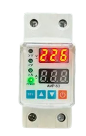
The 63A Voltage Protector is a device designed to safeguard electrical circuits from overvoltage conditions. It is rated for a maximum current of 63 amps, making it suitable for high-power applications. This component ensures the safety of connected equipment by disconnecting the circuit when voltage levels exceed a predefined threshold. It is commonly used in residential, commercial, and industrial settings to protect appliances, machinery, and other sensitive electronics from voltage surges or fluctuations.
Explore Projects Built with 63a voltage protector


Explore Projects Built with 63a voltage protector
Common Applications
- Protection of household appliances such as refrigerators, air conditioners, and washing machines.
- Safeguarding industrial equipment from voltage spikes.
- Ensuring stable operation of commercial electrical systems.
- Preventing damage to sensitive electronics in offices or data centers.
Technical Specifications
The following table outlines the key technical details of the 63A Voltage Protector:
| Parameter | Value |
|---|---|
| Rated Current | 63A |
| Operating Voltage Range | 220V - 240V AC |
| Overvoltage Threshold | Typically 260V (adjustable on some models) |
| Undervoltage Threshold | Typically 170V (adjustable on some models) |
| Response Time | < 1 second |
| Reset Type | Automatic or manual (model-dependent) |
| Dimensions | Varies by model (e.g., 90mm x 60mm x 40mm) |
| Mounting Type | DIN rail or wall-mounted |
| Operating Temperature | -10°C to 50°C |
| Indicator LEDs | Power, Overvoltage, Undervoltage |
Pin Configuration and Descriptions
The 63A Voltage Protector typically has the following terminal connections:
| Terminal | Label | Description |
|---|---|---|
| 1 | L (Line) | Connect to the live wire of the input power supply. |
| 2 | N (Neutral) | Connect to the neutral wire of the input power supply. |
| 3 | L (Load) | Connect to the live wire of the load (protected device). |
| 4 | N (Load) | Connect to the neutral wire of the load (protected device). |
Usage Instructions
How to Use the 63A Voltage Protector in a Circuit
- Power Off the System: Ensure that the power supply is turned off before installation.
- Connect Input Wires:
- Connect the live wire of the power supply to the
L (Line)terminal. - Connect the neutral wire of the power supply to the
N (Neutral)terminal.
- Connect the live wire of the power supply to the
- Connect Output Wires:
- Connect the live wire of the load (appliance or equipment) to the
L (Load)terminal. - Connect the neutral wire of the load to the
N (Load)terminal.
- Connect the live wire of the load (appliance or equipment) to the
- Secure the Connections: Tighten all terminal screws to ensure a secure connection.
- Mount the Device: Install the voltage protector on a DIN rail or wall mount as per the model's design.
- Power On the System: Turn on the power supply and verify that the indicator LEDs are functioning correctly.
Important Considerations and Best Practices
- Ensure that the total load current does not exceed the 63A rating of the device.
- Verify the overvoltage and undervoltage thresholds before connecting sensitive equipment.
- Use appropriate wire gauges to handle the current rating safely.
- Regularly inspect the device for signs of wear or damage.
- For adjustable models, set the voltage thresholds according to the requirements of your application.
Arduino Integration
While the 63A Voltage Protector is not directly programmable, it can be monitored using an Arduino UNO by connecting a voltage sensor to the input and output terminals. Below is an example code snippet to monitor voltage levels:
// Arduino code to monitor voltage levels using a voltage sensor
const int voltagePin = A0; // Analog pin connected to the voltage sensor
float voltage = 0.0;

void setup() {
  Serial.begin(9600); // Initialize serial communication
}

void loop() {
  int sensorValue = analogRead(voltagePin); // Read the sensor value
  voltage = (sensorValue * 5.0) / 1023.0 * 100;
  // Convert the analog value to voltage (adjust scaling factor as needed)

  Serial.print("Voltage: ");
  Serial.print(voltage);
  Serial.println(" V");

  delay(1000); // Wait for 1 second before the next reading
}
Note: Use a voltage divider circuit if the input voltage exceeds the Arduino's analog input range (0-5V).
Troubleshooting and FAQs
Common Issues and Solutions
Device Does Not Power On:
- Check the input power supply connections.
- Verify that the power supply voltage is within the operating range.
Frequent Tripping:
- Ensure that the load current does not exceed 63A.
- Check for unstable power supply or frequent voltage fluctuations.
Indicator LEDs Not Functioning:
- Inspect the device for physical damage or loose connections.
- Replace the device if the internal circuitry is damaged.
Overvoltage/Undervoltage Protection Not Activating:
- Verify the voltage thresholds and adjust them if the model allows.
- Ensure that the device is properly connected to the load and power supply.
FAQs
Q1: Can the 63A Voltage Protector handle three-phase systems?
A1: No, this device is designed for single-phase systems. For three-phase systems, use a dedicated three-phase voltage protector.
Q2: Is the overvoltage threshold adjustable?
A2: Some models allow adjustment of the overvoltage and undervoltage thresholds. Refer to the specific model's manual for instructions.
Q3: What happens after the device trips due to overvoltage?
A3: The device will automatically reset once the voltage returns to a safe range, unless it is a manual reset model.
Q4: Can this device protect against lightning strikes?
A4: While it provides basic surge protection, it is recommended to use a dedicated surge protector for lightning protection.
By following this documentation, users can effectively install, use, and troubleshoot the 63A Voltage Protector to ensure the safety of their electrical systems.