How to Use MyoWare Muscle Sensor V2: Examples, Pinouts, and Specs
Introduction
The MyoWare Muscle Sensor V2 is a compact and versatile sensor designed to detect and measure the electrical activity of muscles (electromyography or EMG). By sensing muscle contractions, this component enables users to control devices, systems, or software based on muscle activity. It is widely used in applications such as robotics, prosthetics, wearable technology, and biofeedback systems.
This sensor is particularly popular in projects requiring human-machine interaction, such as controlling robotic arms, creating gesture-based interfaces, or developing assistive devices for individuals with disabilities.
Explore Projects Built with MyoWare Muscle Sensor V2
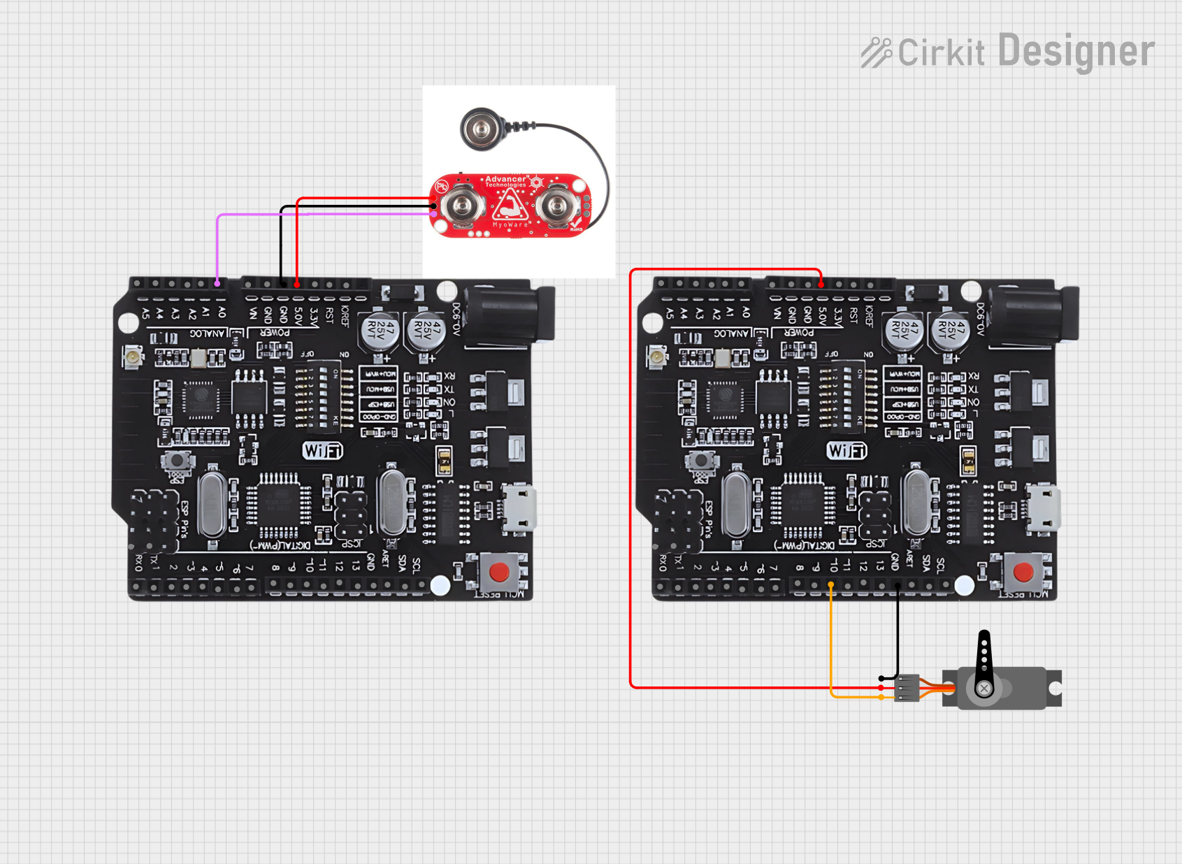
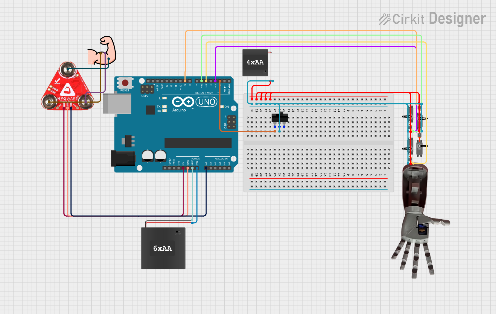
Explore Projects Built with MyoWare Muscle Sensor V2
Technical Specifications
Below are the key technical details of the MyoWare Muscle Sensor V2:
| Specification | Details |
|---|---|
| Manufacturer | MyoWare |
| Part ID | Sensor V2 |
| Operating Voltage | 3.1V to 5.5V |
| Operating Current | ~9mA |
| Output Voltage Range | 0.5V to Vcc (centered at 1.5V for 3.3V systems or 2.5V for 5V systems) |
| Input Impedance | >1MΩ |
| Dimensions | 50mm x 20mm |
| Weight | ~8g |
| Electrode Compatibility | Standard snap-on electrodes |
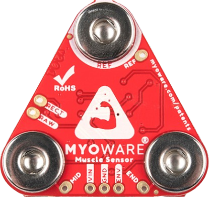
Pin Configuration and Descriptions
The MyoWare Muscle Sensor V2 has the following pin layout:
| Pin Name | Type | Description |
|---|---|---|
VIN |
Power Input | Connect to a 3.1V–5.5V power source. |
GND |
Ground | Connect to the ground of the power supply. |
SIG |
Signal Output | Outputs the processed EMG signal as an analog voltage. |
RAW |
Signal Output | Outputs the raw EMG signal (unfiltered and unamplified). |
REF |
Reference | Optional reference voltage pin for advanced configurations. |
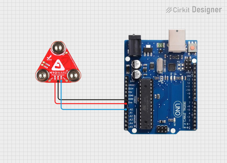
Usage Instructions
How to Use the MyoWare Muscle Sensor V2 in a Circuit
- Power the Sensor: Connect the
VINpin to a 3.3V or 5V power source and theGNDpin to ground. - Attach Electrodes: Snap three electrodes onto the sensor:
- Place the two active electrodes on the muscle you want to monitor.
- Place the reference electrode on a bony or inactive area near the muscle.
- Connect the Signal Output:
- Use the
SIGpin to read the processed EMG signal. - Optionally, use the
RAWpin to access the unprocessed EMG signal for advanced applications.
- Use the
- Read the Signal: Connect the
SIGpin to an analog input on a microcontroller (e.g., Arduino UNO) to process the signal.
Important Considerations and Best Practices
- Electrode Placement: Proper placement of the electrodes is critical for accurate readings. Ensure the skin is clean and dry before attaching the electrodes.
- Power Supply: Use a stable power source to avoid noise in the signal.
- Signal Filtering: If using the
RAWoutput, consider adding external filtering and amplification for better signal quality. - Avoid Noise Sources: Keep the sensor and wires away from high-frequency noise sources, such as motors or power lines.
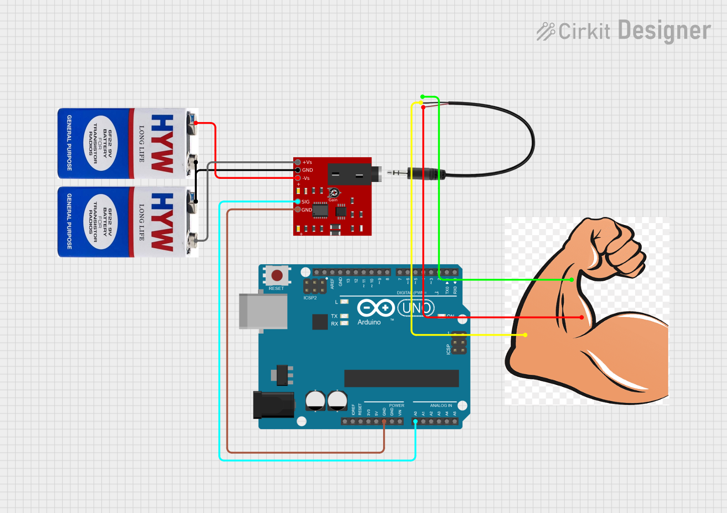
Example: Connecting to an Arduino UNO
Below is an example of how to use the MyoWare Muscle Sensor V2 with an Arduino UNO to read and display muscle activity:
// MyoWare Muscle Sensor V2 Example with Arduino UNO
// Reads the processed EMG signal from the SIG pin and displays it in the Serial Monitor

const int signalPin = A0; // Connect the SIG pin to Arduino analog pin A0
int signalValue = 0;      // Variable to store the sensor reading

void setup() {
  Serial.begin(9600); // Initialize serial communication at 9600 baud
  pinMode(signalPin, INPUT); // Set the signal pin as an input
}

void loop() {
  signalValue = analogRead(signalPin); // Read the analog value from the SIG pin
  Serial.print("Muscle Activity: ");
  Serial.println(signalValue); // Print the value to the Serial Monitor
  delay(100); // Delay for 100ms to reduce data output frequency
}
Notes:
- The
analogRead()function will return a value between 0 and 1023, corresponding to the voltage range of 0V to 5V (on a 5V Arduino). - Use the Serial Monitor in the Arduino IDE to observe the muscle activity in real time.
Troubleshooting and FAQs
Common Issues and Solutions
No Signal Detected:
- Ensure the electrodes are properly attached to the skin and the sensor.
- Verify that the
VINandGNDpins are correctly connected to the power supply.
Noisy or Unstable Signal:
- Check for proper electrode placement and ensure the skin is clean and dry.
- Keep the sensor and wires away from sources of electrical noise.
- Use shielded cables if necessary.
Low Signal Amplitude:
- Ensure the muscle being monitored is actively contracting.
- Verify that the reference electrode is placed on a bony or inactive area.
Arduino Reads Incorrect Values:
- Confirm that the
SIGpin is connected to an analog input pin on the Arduino. - Check the Arduino's power supply voltage (should match the sensor's operating voltage).
- Confirm that the
FAQs
Q: Can I use the MyoWare Muscle Sensor V2 with a 3.3V microcontroller?
A: Yes, the sensor is compatible with both 3.3V and 5V systems. Ensure the VIN pin is supplied with a voltage within the 3.1V–5.5V range.
Q: What type of electrodes should I use?
A: The sensor is compatible with standard snap-on electrodes. Ensure they are high-quality and designed for EMG applications.
Q: Can I use the RAW output for real-time applications?
A: Yes, but the RAW signal may require additional filtering and amplification for optimal performance.
Q: How do I clean the sensor?
A: Use a soft, dry cloth to clean the sensor. Avoid using liquids or abrasive materials.
By following this documentation, you can effectively integrate the MyoWare Muscle Sensor V2 into your projects and achieve reliable results.