Cirkit Designer
Your all-in-one circuit design IDE
Home /
Component Documentation
How to Use MOTOR DEIVE: Examples, Pinouts, and Specs
Introduction
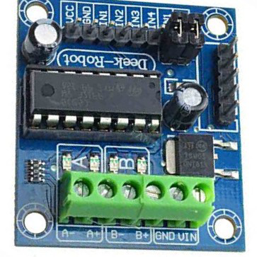
The L293D Motor Drive by PRITHVI is an electronic device designed to control the speed, torque, and direction of electric motors. It converts electrical energy into mechanical energy, making it an essential component for driving machinery and equipment. This motor drive is widely used in robotics, automation systems, and various other applications where precise motor control is required.
Explore Projects Built with MOTOR DEIVE
Arduino UNO Bluetooth-Controlled Motor Driver Circuit
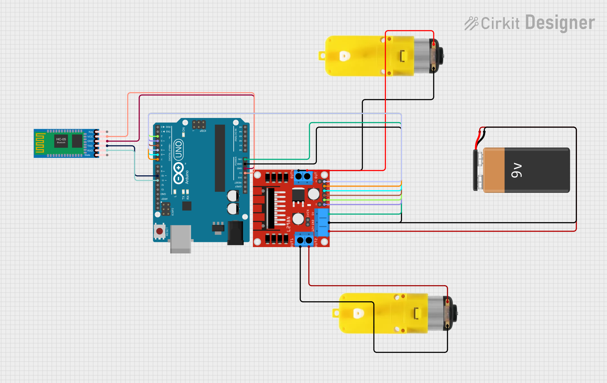
This circuit is a Bluetooth-controlled motor driver system using an Arduino UNO. The Arduino UNO interfaces with an HC-05 Bluetooth module for wireless communication and controls two motors via an H-bridge motor driver. The system is powered by a 9V battery, and the motors are driven by the H-bridge based on commands received through the Bluetooth module.
Arduino UNO Bluetooth-Controlled Robotic System with Motor Drivers and Servo
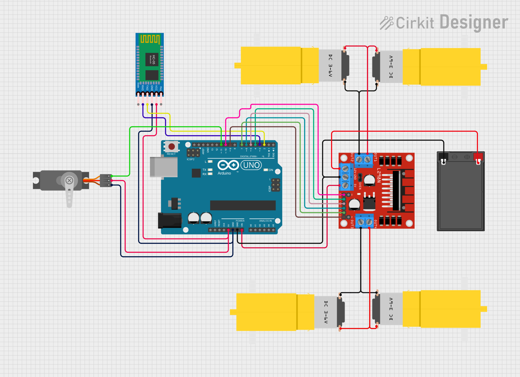
This circuit is a motor control system using an Arduino UNO, an L298N motor driver, and an HC-05 Bluetooth module. The Arduino controls multiple DC motors and a servo motor, with the Bluetooth module enabling wireless communication for remote control.
Battery-Powered DC Motor Control with LED Indicator
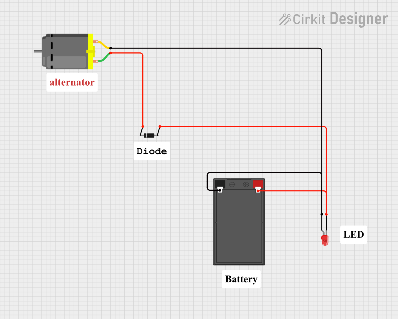
This circuit consists of a DC motor powered by a 12V battery, with a diode for protection against reverse voltage and an LED indicator. The LED is connected in parallel with the motor to indicate when the motor is powered.
ESP32 and L298N Motor Driver Controlled Battery-Powered Robotic Car

This circuit is a motor control system powered by a 12V battery, utilizing an L298N motor driver to control four DC gearmotors. An ESP32 microcontroller is used to send control signals to the motor driver, enabling precise control of the motors for applications such as a robotic vehicle.
Explore Projects Built with MOTOR DEIVE
Arduino UNO Bluetooth-Controlled Motor Driver Circuit
This circuit is a Bluetooth-controlled motor driver system using an Arduino UNO. The Arduino UNO interfaces with an HC-05 Bluetooth module for wireless communication and controls two motors via an H-bridge motor driver. The system is powered by a 9V battery, and the motors are driven by the H-bridge based on commands received through the Bluetooth module.
Arduino UNO Bluetooth-Controlled Robotic System with Motor Drivers and Servo
This circuit is a motor control system using an Arduino UNO, an L298N motor driver, and an HC-05 Bluetooth module. The Arduino controls multiple DC motors and a servo motor, with the Bluetooth module enabling wireless communication for remote control.
Battery-Powered DC Motor Control with LED Indicator
This circuit consists of a DC motor powered by a 12V battery, with a diode for protection against reverse voltage and an LED indicator. The LED is connected in parallel with the motor to indicate when the motor is powered.
ESP32 and L298N Motor Driver Controlled Battery-Powered Robotic Car
This circuit is a motor control system powered by a 12V battery, utilizing an L298N motor driver to control four DC gearmotors. An ESP32 microcontroller is used to send control signals to the motor driver, enabling precise control of the motors for applications such as a robotic vehicle.
Technical Specifications
Key Technical Details
| Parameter | Value |
|---|---|
| Manufacturer | PRITHVI |
| Part ID | L293D MOTOR DRIVE |
| Operating Voltage | 4.5V to 36V |
| Output Current | 600mA per channel (peak 1.2A) |
| Number of Channels | 4 |
| Logic Voltage | 5V |
| Power Dissipation | 5W |
| Operating Temperature | -40°C to 150°C |
Pin Configuration and Descriptions
| Pin No. | Pin Name | Description |
|---|---|---|
| 1 | Enable 1 | Enables the first pair of drivers (1,2EN) |
| 2 | Input 1 | Input for the first driver |
| 3 | Output 1 | Output for the first driver |
| 4 | GND | Ground |
| 5 | GND | Ground |
| 6 | Output 2 | Output for the second driver |
| 7 | Input 2 | Input for the second driver |
| 8 | Vcc2 | Supply voltage for the motors (4.5V to 36V) |
| 9 | Enable 2 | Enables the second pair of drivers (3,4EN) |
| 10 | Input 3 | Input for the third driver |
| 11 | Output 3 | Output for the third driver |
| 12 | GND | Ground |
| 13 | GND | Ground |
| 14 | Output 4 | Output for the fourth driver |
| 15 | Input 4 | Input for the fourth driver |
| 16 | Vcc1 | Supply voltage for the logic (5V) |
Usage Instructions
How to Use the Component in a Circuit
Power Supply:
- Connect Vcc1 (Pin 16) to a 5V power supply.
- Connect Vcc2 (Pin 8) to the motor power supply (4.5V to 36V).
- Connect all GND pins (Pins 4, 5, 12, 13) to the ground of the power supply.
Motor Connections:
- Connect the motor terminals to the output pins (Pins 3, 6, 11, 14).
Control Inputs:
- Connect the control signals to the input pins (Pins 2, 7, 10, 15).
- Use the enable pins (Pins 1, 9) to enable or disable the motor drivers.
Important Considerations and Best Practices
- Ensure that the power supply voltage does not exceed the specified range.
- Use appropriate heat sinks if the device is operating at high currents to prevent overheating.
- Decouple the power supply with capacitors to reduce noise and improve stability.
- Avoid short circuits between the output pins to prevent damage to the device.
Example: Connecting to an Arduino UNO
// Arduino UNO and L293D Motor Drive Example

// Define motor control pins
const int enablePin1 = 9; // Enable pin for motor 1
const int inputPin1 = 2;  // Input pin 1 for motor 1
const int inputPin2 = 3;  // Input pin 2 for motor 1

void setup() {
  // Set control pins as outputs
  pinMode(enablePin1, OUTPUT);
  pinMode(inputPin1, OUTPUT);
  pinMode(inputPin2, OUTPUT);

  // Enable the motor driver
  digitalWrite(enablePin1, HIGH);
}

void loop() {
  // Rotate motor clockwise
  digitalWrite(inputPin1, HIGH);
  digitalWrite(inputPin2, LOW);
  delay(2000); // Run for 2 seconds

  // Stop the motor
  digitalWrite(inputPin1, LOW);
  digitalWrite(inputPin2, LOW);
  delay(1000); // Stop for 1 second

  // Rotate motor counterclockwise
  digitalWrite(inputPin1, LOW);
  digitalWrite(inputPin2, HIGH);
  delay(2000); // Run for 2 seconds

  // Stop the motor
  digitalWrite(inputPin1, LOW);
  digitalWrite(inputPin2, LOW);
  delay(1000); // Stop for 1 second
}
Troubleshooting and FAQs
Common Issues Users Might Face
Motor Not Running:
- Check the power supply connections and ensure the correct voltage is applied.
- Verify that the enable pins are set to HIGH.
- Ensure that the input control signals are correctly configured.
Overheating:
- Ensure that the current does not exceed the maximum rating.
- Use heat sinks or cooling mechanisms if necessary.
Noise and Instability:
- Use decoupling capacitors on the power supply lines.
- Ensure proper grounding and minimize the length of the ground connections.
Solutions and Tips for Troubleshooting
- Check Connections: Double-check all connections to ensure they are secure and correctly placed.
- Measure Voltages: Use a multimeter to measure the voltages at various points in the circuit to identify any discrepancies.
- Use Proper Heat Management: If the device is overheating, consider using heat sinks or fans to dissipate heat effectively.
- Consult the Datasheet: Refer to the manufacturer's datasheet for detailed information and additional troubleshooting tips.
By following this documentation, users can effectively utilize the L293D Motor Drive in their projects, ensuring reliable and efficient motor control.