Cirkit Designer LogoCirkit DesignerYour all-in-one circuit design IDE Launch Cirkit Designer App

How to Use Power Supply: Examples, Pinouts, and Specs

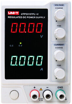
Image of Power SupplyDesign with Power Supply in Cirkit Designer

Introduction

A Power Supply is an essential component in any electronic system. It converts electrical power from a source, such as the mains AC (Alternating Current) or a battery, into a stable DC (Direct Current) voltage and current to operate a variety of electronic devices and circuits. Power supplies are used in everything from consumer electronics to industrial machinery, ensuring that devices receive the correct voltage and current for their operation.

Explore Projects Built with Power Supply

Use Cirkit Designer to design, explore, and prototype these projects online. Some projects support real-time simulation. Click "Open Project" to start designing instantly!
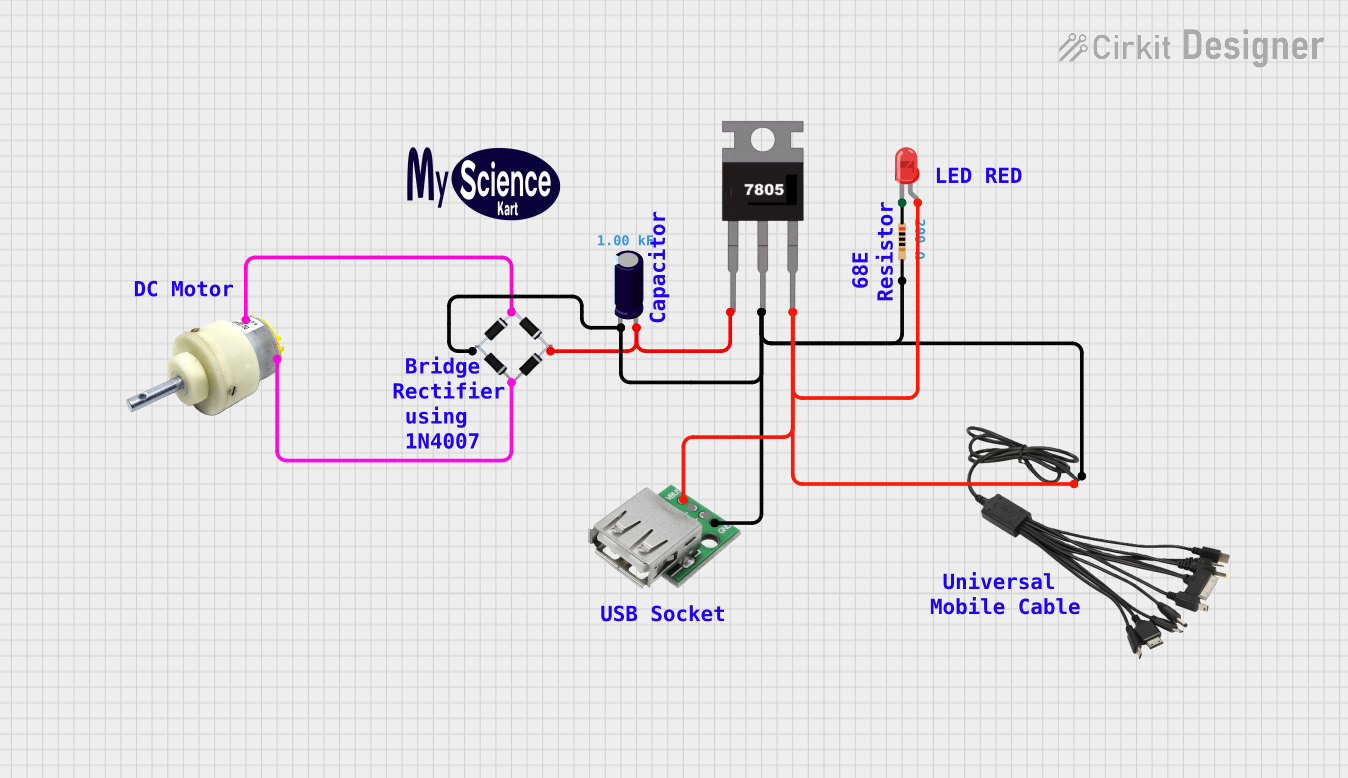
Image of USB-Powered DC Gear Motor with LED Indicator: A project utilizing Power Supply in a practical application
USB-Powered DC Gear Motor with LED Indicator

This circuit appears to be a power supply unit with a bridge rectifier connected to a DC gear motor, indicating it is designed to convert AC to DC power for the motor. An electrolytic capacitor is used for smoothing the DC output, and a 7805 voltage regulator is included to provide a stable 5V output. Additionally, there is an LED with a series resistor, likely serving as a power indicator light.

Open Project in Cirkit Designer
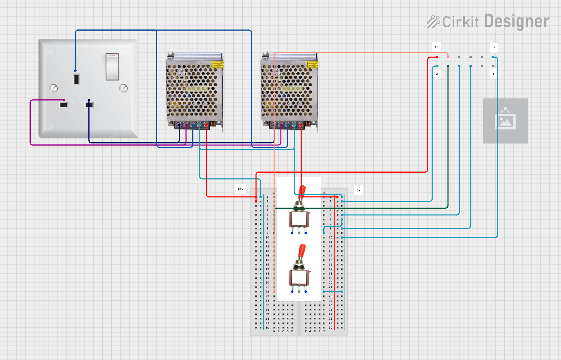
Image of Dual 5V Power Supply Distribution Circuit with Toggle Switch Control: A project utilizing Power Supply in a practical application
Dual 5V Power Supply Distribution Circuit with Toggle Switch Control

This circuit consists of two 5V 5A power supplies connected to an AC wall plug point, providing DC output through a 12-way connector. The ground connections from both power supplies are interconnected and also connected to the ground pins of two toggle switches. The DC outputs from the power supplies are separately connected to different pins on the 12-way connector, with each power supply output being switchable via one of the toggle switches.

Open Project in Cirkit Designer
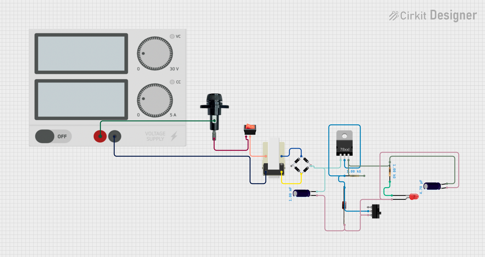
Image of AC to DC Power Supply with Voltage Regulation and Overcurrent Protection: A project utilizing Power Supply in a practical application
AC to DC Power Supply with Voltage Regulation and Overcurrent Protection

This circuit appears to be a power supply unit with a transformer for stepping down voltage, a bridge rectifier for converting AC to DC, and a voltage regulator for stabilizing the output voltage. It includes a Zener diode for overvoltage protection, capacitors for smoothing out ripples in the DC supply, and a fuse for overcurrent protection. A toggle switch and a rocker switch are used to control the power flow, and there is an LED indicator connected through resistors, likely for power-on indication.

Open Project in Cirkit Designer

Common Applications and Use Cases

Technical Specifications

Key Technical Details

Pin Configuration and Descriptions

Pin Number Description Notes
1 AC Input Connect to AC mains or source
2 Ground (Earth) Safety ground connection
3 DC Output Positive Positive voltage output
4 DC Output Negative Ground or negative voltage output

Usage Instructions

How to Use the Power Supply in a Circuit

  1. Connect the AC Input: Ensure the power supply is not plugged into an AC source. Connect the AC input pins to your AC source, respecting the correct voltage and polarity.
  2. Grounding: Connect the ground pin to the earth ground in your system for safety and noise reduction.
  3. Connect the DC Output: Attach the positive and negative outputs to your circuit, ensuring that the voltage and current ratings are within the specifications of your device.
  4. Power On: Once all connections are secure, plug the power supply into the AC source and switch it on.

Important Considerations and Best Practices

Troubleshooting and FAQs

Common Issues Users Might Face

Solutions and Tips for Troubleshooting

FAQs

Example Connection to an Arduino UNO

// No direct code is involved in connecting a power supply to an Arduino UNO.
// However, it is crucial to ensure that the power supply's output voltage
// matches the requirements of the Arduino UNO (typically 5V or 3.3V for logic).

// Always consult the Arduino UNO's specifications before connecting a power supply.

Note: The Arduino UNO can be powered via the USB connection, the barrel jack, or the VIN pin. When using an external power supply, ensure it complies with the Arduino's input voltage specifications (6-20V for barrel jack, recommended 7-12V).

Remember, this documentation is a generic guide and may not cover all aspects of your specific power supply model. Always consult the manufacturer's datasheet for precise information.