
How to Use EBM001: Examples, Pinouts, and Specs
 Design with EBM001 in Cirkit Designer
Introduction
The EBM001 is a versatile electronic component, commonly used as a motor or actuator in a wide range of applications. It is designed to efficiently and reliably convert electrical energy into mechanical motion, making it an essential component in robotics, automation systems, and industrial machinery. Its compact design and high performance make it suitable for both hobbyist projects and professional applications.
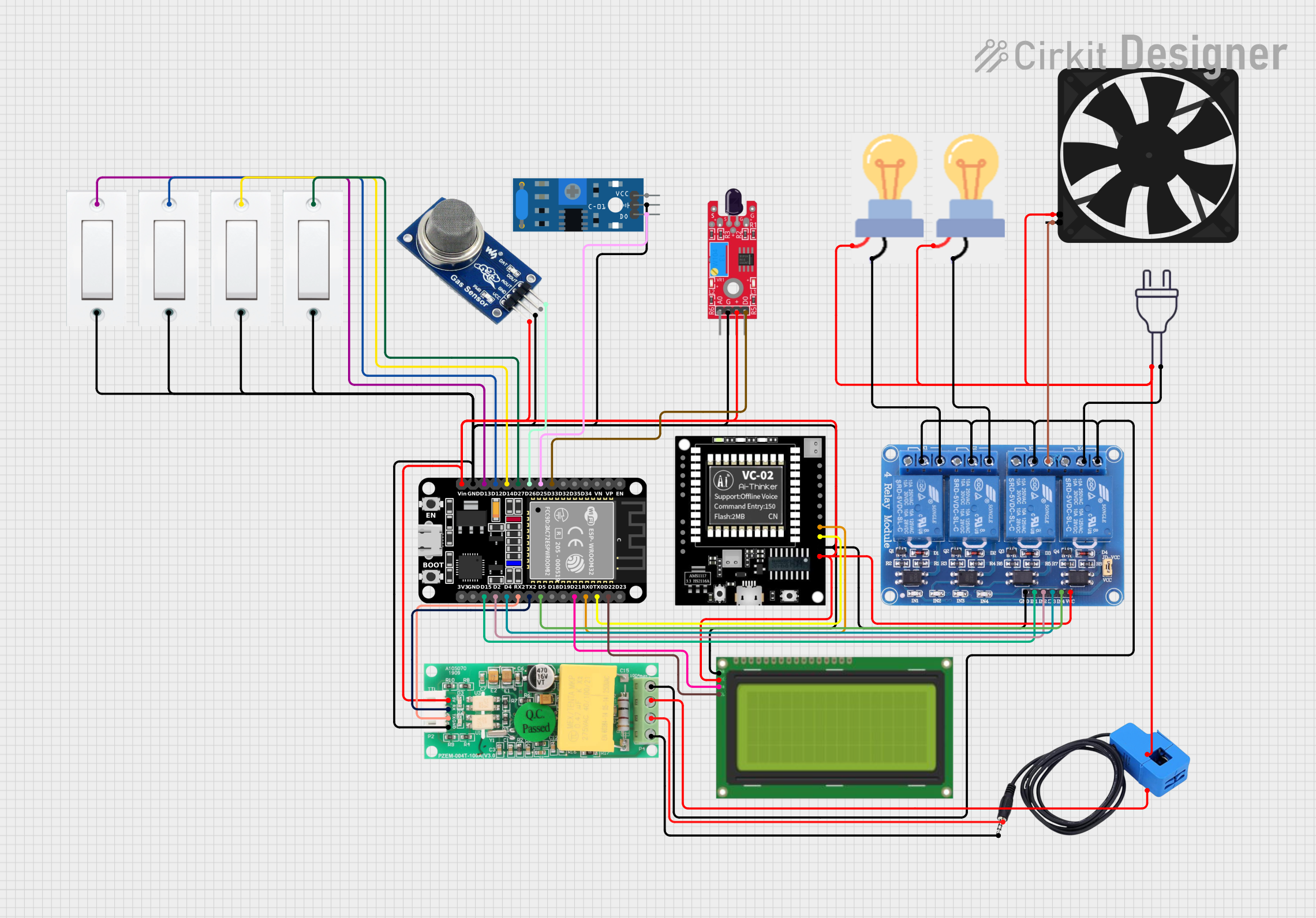
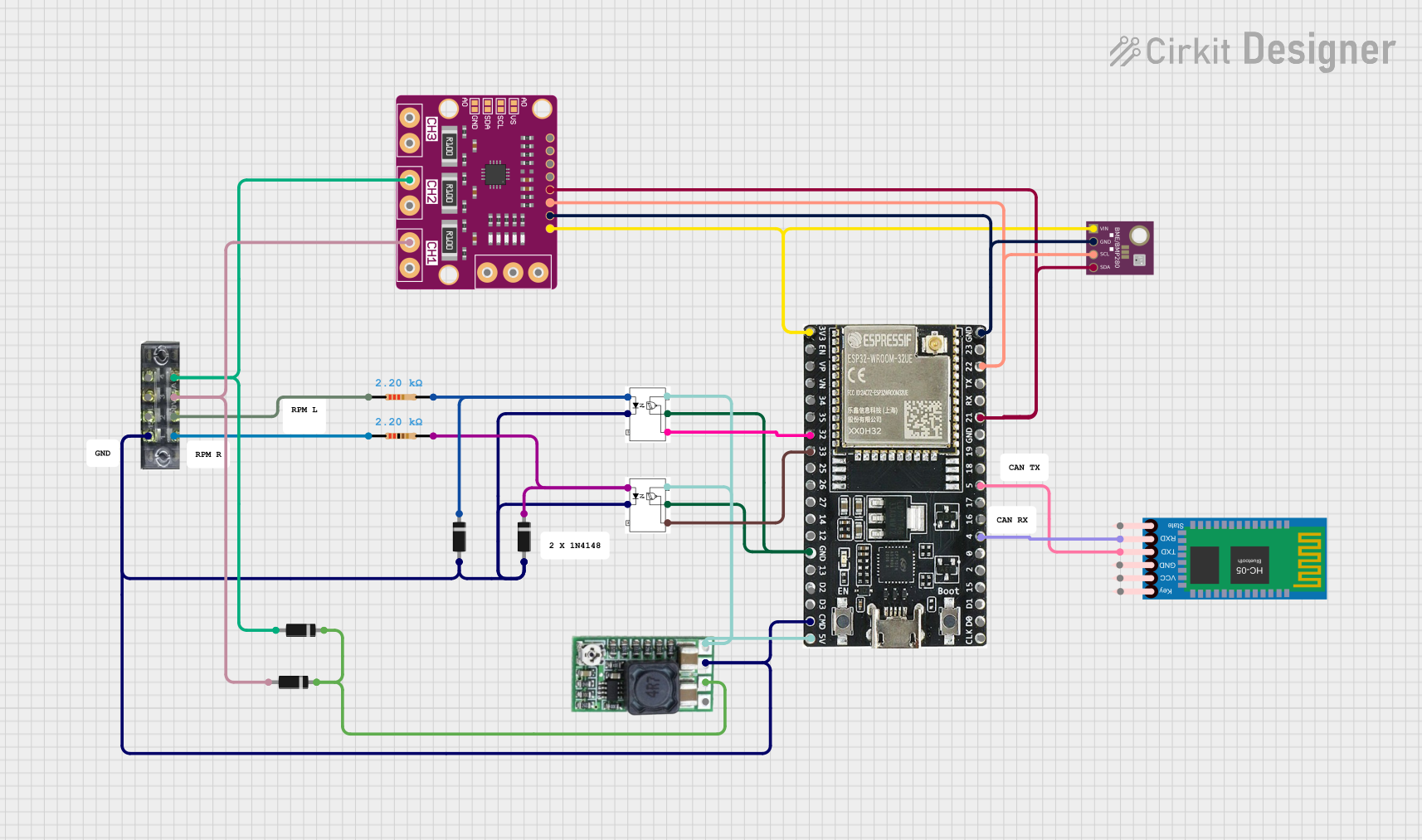
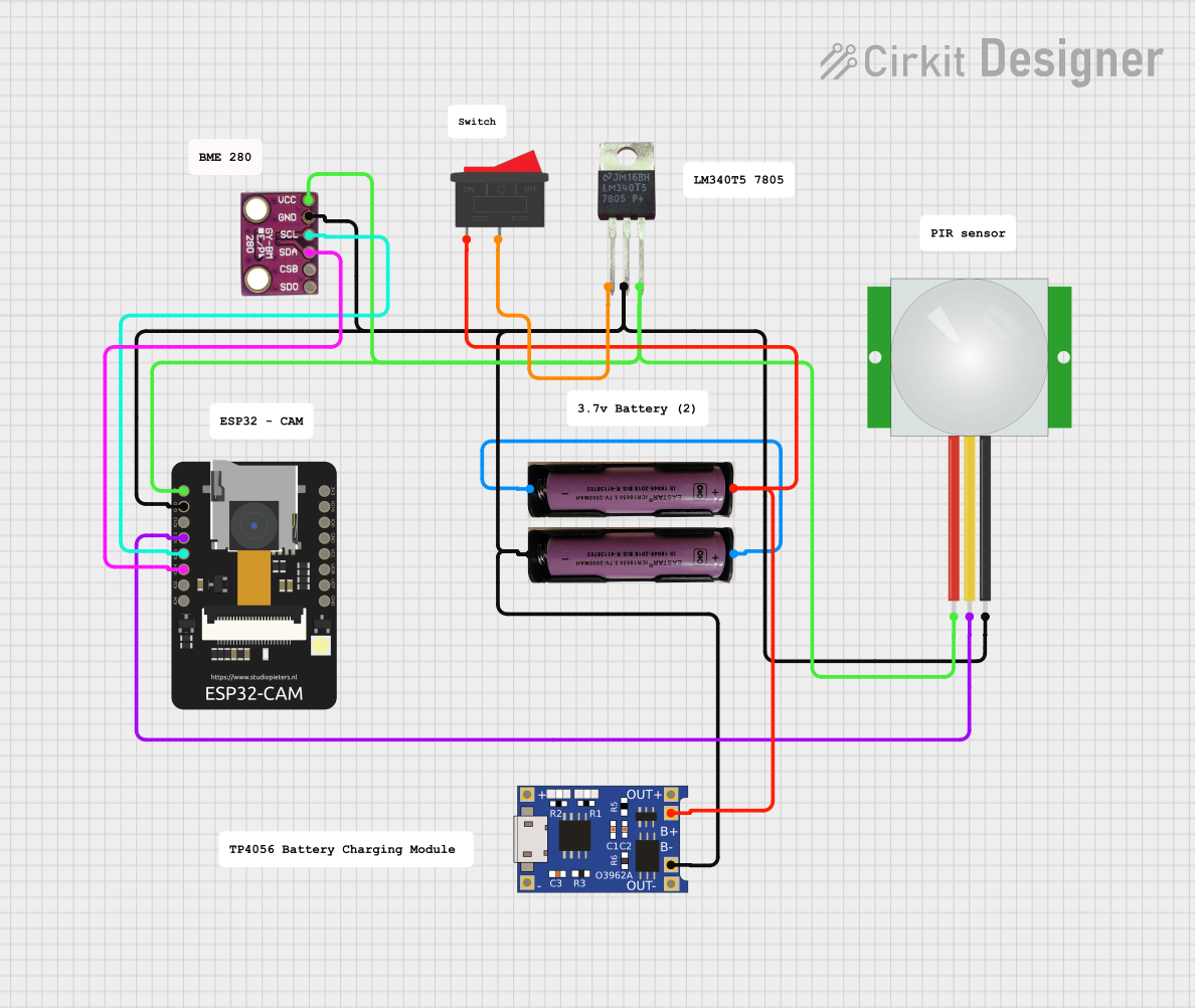
Explore Projects Built with EBM001
 Open Project in Cirkit Designer
 Open Project in Cirkit Designer
 Open Project in Cirkit Designer
 Open Project in Cirkit Designer
Explore Projects Built with EBM001
Open Project in Cirkit DesignerOpen Project in Cirkit DesignerOpen Project in Cirkit DesignerOpen Project in Cirkit DesignerCommon Applications
- Robotics (e.g., robotic arms, mobile robots)
- Conveyor systems in industrial automation
- Precision control systems in manufacturing
- Actuators in smart home devices
- Educational and DIY electronics projects
Technical Specifications
Key Technical Details
| Parameter | Value |
|---|---|
| Operating Voltage | 5V to 12V |
| Rated Current | 500mA |
| Stall Current | 1.2A |
| Maximum Torque | 1.5 kg·cm |
| Speed (No Load) | 200 RPM at 12V |
| Operating Temperature | -10°C to 60°C |
| Dimensions | 35mm x 25mm x 20mm |
| Weight | 50g |
Pin Configuration and Descriptions
| Pin Number | Pin Name | Description |
|---|---|---|
| 1 | VCC | Power supply input (5V to 12V) |
| 2 | GND | Ground connection |
| 3 | IN1 | Control input 1 for direction control |
| 4 | IN2 | Control input 2 for direction control |
| 5 | EN | Enable pin (PWM input for speed control) |
Usage Instructions
How to Use the EBM001 in a Circuit
- Power Supply: Connect the VCC pin to a regulated power source (5V to 12V) and the GND pin to the ground of your circuit.
- Direction Control: Use the IN1 and IN2 pins to control the rotation direction of the motor:
- Set IN1 to HIGH and IN2 to LOW for clockwise rotation.
- Set IN1 to LOW and IN2 to HIGH for counterclockwise rotation.
- Speed Control: Connect the EN pin to a PWM signal from a microcontroller (e.g., Arduino) to control the motor's speed. A higher duty cycle corresponds to a higher speed.
- Protection: Use a flyback diode across the motor terminals to protect the circuit from voltage spikes caused by inductive loads.
Example: Connecting EBM001 to an Arduino UNO
Below is an example of how to control the EBM001 using an Arduino UNO:
// Define pin connections
const int IN1 = 8;  // Control pin 1
const int IN2 = 9;  // Control pin 2
const int EN = 10;  // Enable pin (PWM)

// Setup function to initialize pins
void setup() {
  pinMode(IN1, OUTPUT);  // Set IN1 as output
  pinMode(IN2, OUTPUT);  // Set IN2 as output
  pinMode(EN, OUTPUT);   // Set EN as output
}

// Loop function to control motor
void loop() {
  // Rotate motor clockwise at 50% speed
  digitalWrite(IN1, HIGH);  // Set IN1 HIGH
  digitalWrite(IN2, LOW);   // Set IN2 LOW
  analogWrite(EN, 128);     // Set PWM duty cycle to 50% (128/255)

  delay(2000);  // Run for 2 seconds

  // Rotate motor counterclockwise at full speed
  digitalWrite(IN1, LOW);   // Set IN1 LOW
  digitalWrite(IN2, HIGH);  // Set IN2 HIGH
  analogWrite(EN, 255);     // Set PWM duty cycle to 100% (255/255)

  delay(2000);  // Run for 2 seconds

  // Stop the motor
  digitalWrite(IN1, LOW);   // Set IN1 LOW
  digitalWrite(IN2, LOW);   // Set IN2 LOW
  analogWrite(EN, 0);       // Set PWM duty cycle to 0%

  delay(2000);  // Wait for 2 seconds before repeating
}
Important Considerations
- Ensure the power supply voltage matches the operating voltage range of the EBM001.
- Avoid exceeding the rated current to prevent overheating or damage.
- Use appropriate heat dissipation methods if the motor operates continuously at high loads.
- Always include a flyback diode to protect the circuit from voltage spikes.
Troubleshooting and FAQs
Common Issues and Solutions
Motor Does Not Spin
- Cause: Incorrect wiring or insufficient power supply.
- Solution: Double-check all connections and ensure the power supply provides adequate voltage and current.
Motor Spins in the Wrong Direction
- Cause: IN1 and IN2 pins are not configured correctly.
- Solution: Swap the HIGH/LOW states of IN1 and IN2 to reverse the direction.
Motor Runs Erratically
- Cause: Noise or instability in the power supply or PWM signal.
- Solution: Use a decoupling capacitor near the VCC and GND pins and ensure a stable PWM signal.
Motor Overheats
- Cause: Prolonged operation at high current or torque.
- Solution: Reduce the load on the motor or add a heat sink for better thermal management.
FAQs
Can I use the EBM001 with a 3.3V microcontroller?
- Yes, but you will need a level shifter or a motor driver circuit to interface the 3.3V logic with the motor's control pins.
What is the maximum PWM frequency supported by the EN pin?
- The EN pin supports PWM frequencies up to 20 kHz.
Can the EBM001 be used in battery-powered applications?
- Yes, as long as the battery provides a stable voltage within the operating range and sufficient current.
Is the EBM001 waterproof?
- No, the EBM001 is not waterproof. Avoid exposing it to moisture or liquids.