How to Use ADU-5/7: Examples, Pinouts, and Specs
Introduction
The ADU-5/7, manufactured by Ecumaster, is a high-performance analog-to-digital converter (ADC) designed to convert analog signals into digital data for processing in electronic systems. This component is widely used in applications requiring precise signal measurement and processing, such as automotive systems, industrial automation, and data acquisition systems. Its robust design and reliable performance make it suitable for both professional and hobbyist projects.
Explore Projects Built with ADU-5/7
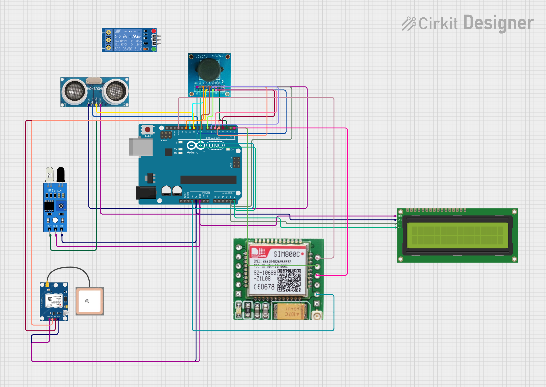
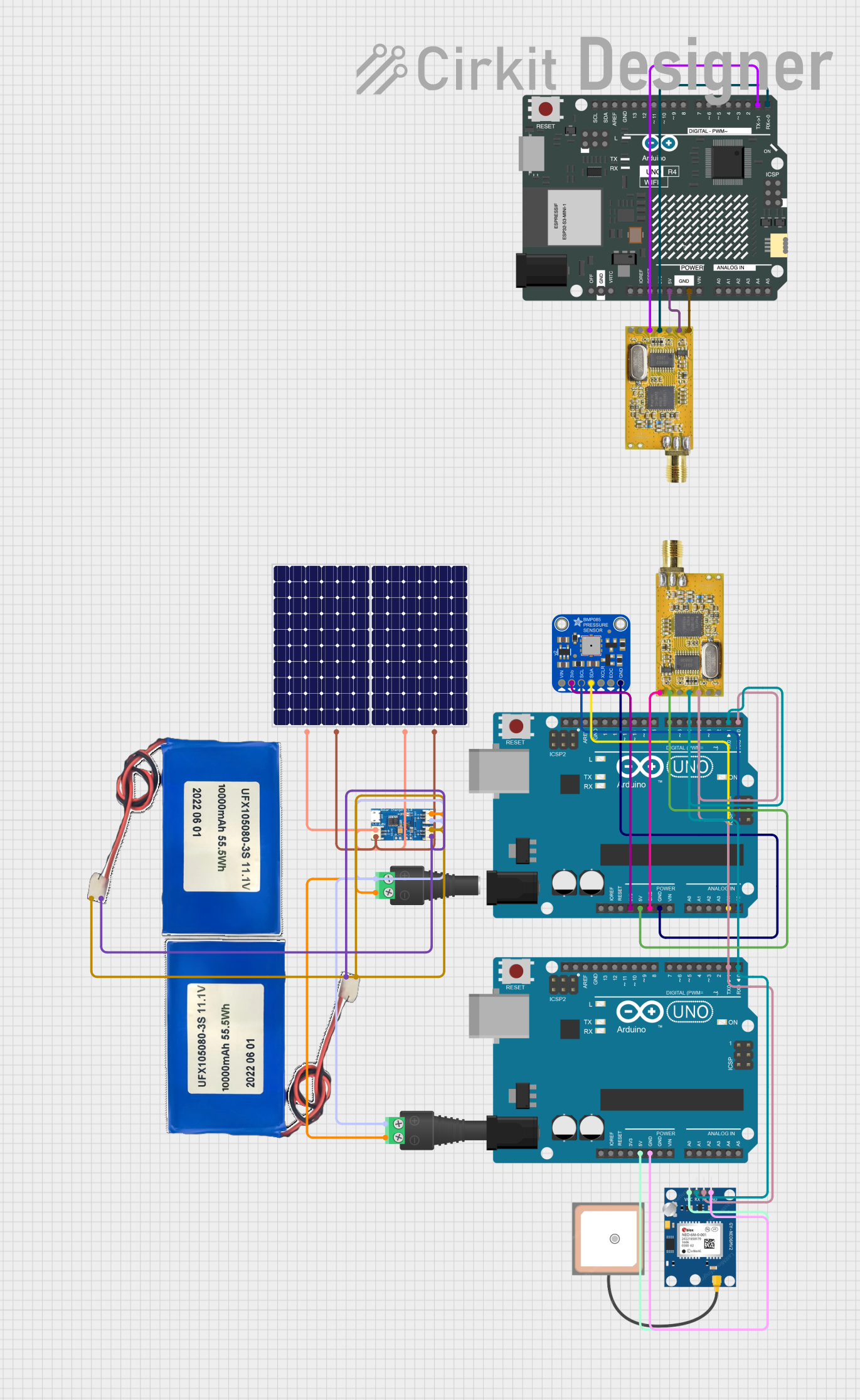
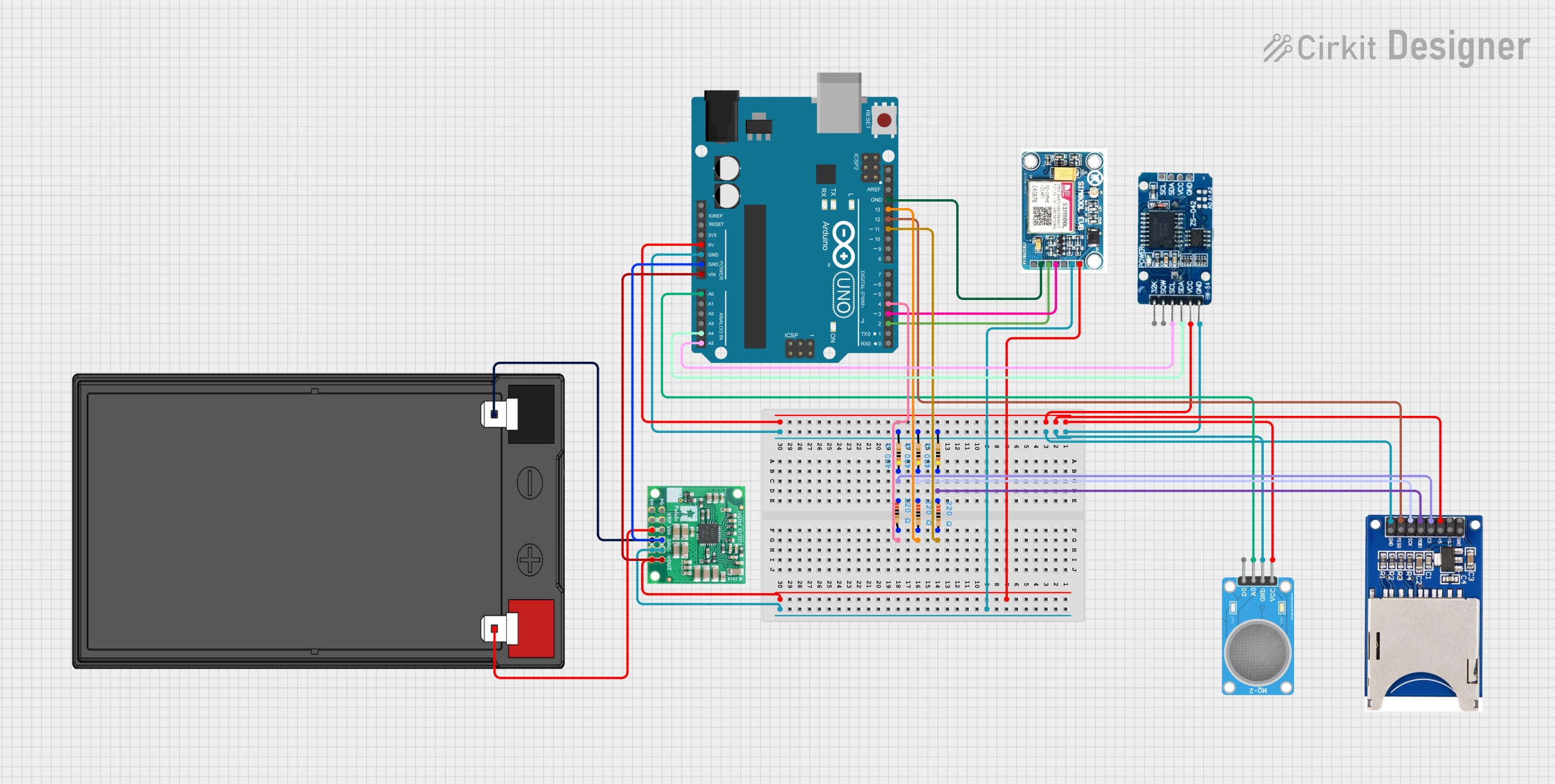
Explore Projects Built with ADU-5/7
Common Applications and Use Cases
- Automotive sensor data acquisition (e.g., temperature, pressure, and speed sensors)
- Industrial process monitoring and control
- Signal processing in embedded systems
- Data logging and telemetry systems
- Integration with microcontrollers and development boards (e.g., Arduino, Raspberry Pi)
Technical Specifications
The ADU-5/7 is available in two variants, ADU-5 and ADU-7, which differ in the number of input channels. Below are the key technical details:
General Specifications
| Parameter | Value |
|---|---|
| Input Voltage Range | 0–5 V |
| Resolution | 12-bit |
| Sampling Rate | Up to 1 kHz per channel |
| Number of Channels | 5 (ADU-5) / 7 (ADU-7) |
| Communication Interface | SPI (Serial Peripheral Interface) |
| Operating Voltage | 3.3 V or 5 V |
| Power Consumption | < 50 mW |
| Operating Temperature | -40°C to +85°C |
| Package Type | DIP/SMD |
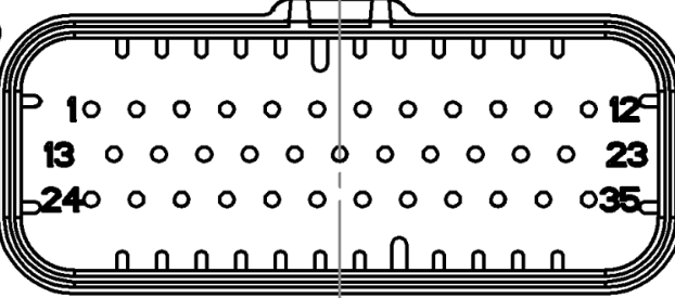
Pin Configuration and Descriptions
The ADU-5/7 features a standard pinout for easy integration into circuits. Below is the pin configuration:
| Pin Number | Pin Name | Description |
|---|---|---|
| 1 | VCC | Power supply input (3.3 V or 5 V) |
| 2 | GND | Ground |
| 3 | CS | Chip Select (active low) for SPI communication |
| 4 | SCLK | Serial Clock input for SPI |
| 5 | MISO | Master In Slave Out (data output) |
| 6 | CH1 | Analog input channel 1 |
| 7 | CH2 | Analog input channel 2 |
| 8 | CH3 | Analog input channel 3 |
| 9 | CH4 | Analog input channel 4 |
| 10 | CH5 | Analog input channel 5 |
| 11 | CH6 (ADU-7) | Analog input channel 6 (ADU-7 only) |
| 12 | CH7 (ADU-7) | Analog input channel 7 (ADU-7 only) |
Usage Instructions
How to Use the ADU-5/7 in a Circuit
- Power Supply: Connect the VCC pin to a 3.3 V or 5 V power source and the GND pin to ground.
- SPI Communication: Connect the CS, SCLK, and MISO pins to the corresponding SPI pins on your microcontroller or development board.
- Analog Inputs: Connect the analog signals to the CH1–CH5 (or CH1–CH7 for ADU-7) pins. Ensure the input voltage does not exceed the 0–5 V range.
- Initialization: Configure the SPI interface on your microcontroller to communicate with the ADU-5/7. Set the appropriate clock speed and data format.
- Data Acquisition: Use SPI commands to read digital data from the ADU-5/7. Process the data as needed in your application.
Important Considerations and Best Practices
- Input Voltage Range: Ensure that the analog input signals are within the 0–5 V range to prevent damage to the ADC.
- Noise Reduction: Use proper grounding and decoupling capacitors to minimize noise in the circuit.
- Sampling Rate: Adjust the sampling rate based on your application's requirements to balance speed and accuracy.
- SPI Configuration: Verify the SPI clock polarity and phase settings to ensure proper communication with the ADU-5/7.
Example Code for Arduino UNO
Below is an example of how to interface the ADU-5/7 with an Arduino UNO using SPI:
#include <SPI.h>

// Define SPI pins for ADU-5/7
const int CS_PIN = 10; // Chip Select pin

void setup() {
  // Initialize Serial Monitor for debugging
  Serial.begin(9600);

  // Configure SPI settings
  SPI.begin();
  pinMode(CS_PIN, OUTPUT);
  digitalWrite(CS_PIN, HIGH); // Set CS pin to HIGH (inactive)

  Serial.println("ADU-5/7 Initialized");
}

uint16_t readADC(uint8_t channel) {
  // Ensure the channel is valid (1 to 5 for ADU-5, 1 to 7 for ADU-7)
  if (channel < 1 || channel > 7) {
    Serial.println("Invalid channel");
    return 0;
  }

  // Start SPI communication
  digitalWrite(CS_PIN, LOW); // Activate CS pin
  SPI.transfer(0x80 | (channel - 1)); // Send channel selection command
  uint8_t highByte = SPI.transfer(0x00); // Read high byte of ADC data
  uint8_t lowByte = SPI.transfer(0x00);  // Read low byte of ADC data
  digitalWrite(CS_PIN, HIGH); // Deactivate CS pin

  // Combine high and low bytes into a 12-bit value
  uint16_t adcValue = (highByte << 8) | lowByte;
  return adcValue;
}

void loop() {
  // Read ADC value from channel 1
  uint16_t adcValue = readADC(1);
  Serial.print("Channel 1 ADC Value: ");
  Serial.println(adcValue);

  delay(1000); // Wait 1 second before the next reading
}
Troubleshooting and FAQs
Common Issues and Solutions
No Data Output:
- Ensure the SPI pins are correctly connected to the microcontroller.
- Verify that the CS pin is properly toggled during communication.
Incorrect ADC Values:
- Check that the input voltage is within the 0–5 V range.
- Verify the SPI clock settings (polarity and phase) match the ADU-5/7 requirements.
Noise in Readings:
- Use decoupling capacitors near the power supply pins.
- Ensure proper grounding and shielding of analog input signals.
Overheating:
- Verify that the power supply voltage does not exceed the specified range.
- Check for short circuits in the circuit connections.
FAQs
Q: Can the ADU-5/7 be used with 3.3 V systems?
A: Yes, the ADU-5/7 is compatible with both 3.3 V and 5 V systems.
Q: What is the maximum sampling rate?
A: The ADU-5/7 supports a maximum sampling rate of 1 kHz per channel.
Q: How many channels can I use simultaneously?
A: The ADU-5 supports up to 5 channels, while the ADU-7 supports up to 7 channels.
Q: Is the ADU-5/7 compatible with Arduino?
A: Yes, the ADU-5/7 can be easily interfaced with Arduino using the SPI library.