How to Use Arduino Uno WiFi R3 (ATmega328P+ESP8266): Examples, Pinouts, and Specs
Introduction
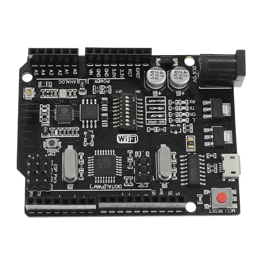
The Arduino Uno WiFi R3 (ATmega328P+ESP8266) is a versatile microcontroller board that combines the functionality of the classic Arduino Uno with built-in WiFi capabilities, thanks to the integrated ESP8266 module. This board is ideal for Internet of Things (IoT) projects, enabling wireless communication and control. It is based on the ATmega328P microcontroller and is compatible with the Arduino IDE, making it beginner-friendly while offering advanced features for experienced users.
Explore Projects Built with Arduino Uno WiFi R3 (ATmega328P+ESP8266)
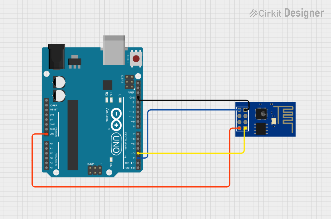
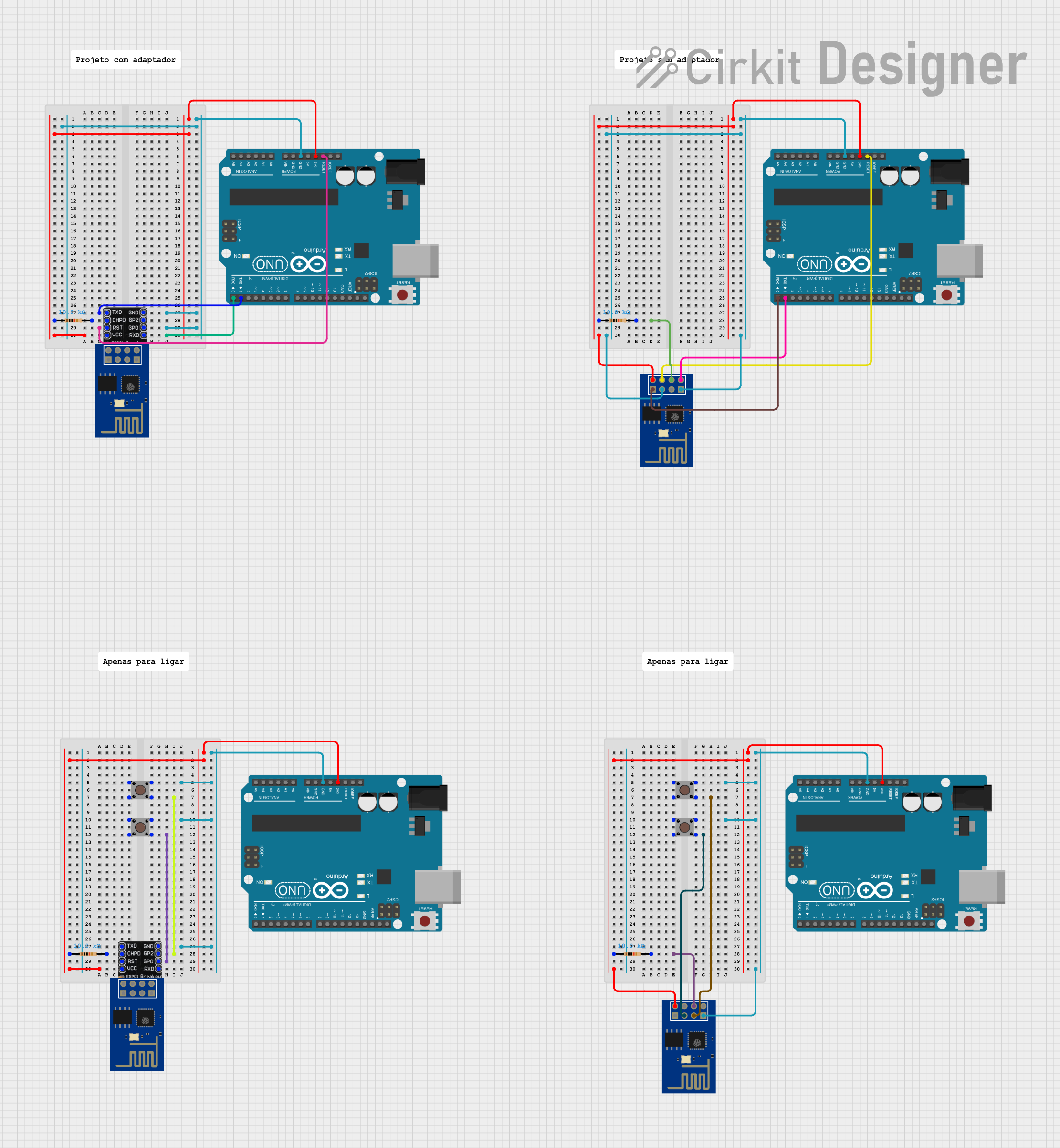
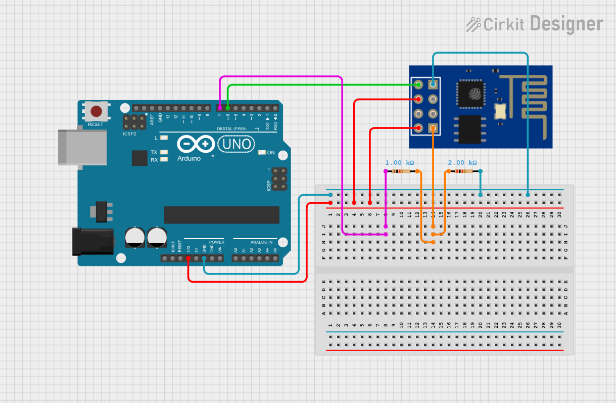
Explore Projects Built with Arduino Uno WiFi R3 (ATmega328P+ESP8266)
Common Applications and Use Cases
- IoT projects, such as smart home automation
- Wireless sensor networks
- Remote data logging and monitoring
- Web-based device control
- Prototyping WiFi-enabled devices
Technical Specifications
Key Technical Details
| Parameter | Specification |
|---|---|
| Microcontroller | ATmega328P |
| WiFi Module | ESP8266 |
| Operating Voltage | 5V |
| Input Voltage (recommended) | 7-12V |
| Input Voltage (limit) | 6-20V |
| Digital I/O Pins | 14 (6 PWM outputs) |
| Analog Input Pins | 6 |
| Flash Memory | 32 KB (ATmega328P) + 1 MB (ESP8266) |
| SRAM | 2 KB (ATmega328P) |
| EEPROM | 1 KB (ATmega328P) |
| Clock Speed | 16 MHz |
| Communication Interfaces | UART, SPI, I2C |
| WiFi Standards | 802.11 b/g/n |
Pin Configuration and Descriptions
ATmega328P Pinout
| Pin Number | Pin Name | Description |
|---|---|---|
| 1-14 | Digital Pins | General-purpose I/O pins (D0-D13), D3, D5, D6, |
| D9, D10, and D11 support PWM output. | ||
| A0-A5 | Analog Pins | Analog input pins (10-bit resolution). |
| 3.3V | 3.3V Output | Provides 3.3V output for low-power peripherals. |
| 5V | 5V Output | Provides 5V output for external components. |
| GND | Ground | Common ground for the circuit. |
| VIN | Voltage Input | Input voltage to the board (7-12V recommended). |
ESP8266 Pinout
| Pin Name | Description |
|---|---|
| TX | Transmit pin for serial communication. |
| RX | Receive pin for serial communication. |
| EN | Enable pin to activate the ESP8266 module. |
| GPIO0 | General-purpose I/O pin. |
| GPIO2 | General-purpose I/O pin. |
| CH_PD | Chip power-down pin (active high). |
Usage Instructions
How to Use the Component in a Circuit
Powering the Board:
- Use a USB cable to power the board via the USB port.
- Alternatively, connect an external power supply (7-12V) to the VIN pin or DC barrel jack.
Programming the ATmega328P:
- Connect the board to your computer using a USB cable.
- Open the Arduino IDE, select the correct board (
Arduino Uno WiFi) and port. - Write your sketch and upload it to the board.
Using the ESP8266 WiFi Module:
- The ESP8266 module communicates with the ATmega328P via serial communication.
- Use AT commands or libraries like
WiFiEspto configure and control the WiFi module.
Connecting to WiFi:
- Ensure the ESP8266 is enabled (EN pin is high).
- Use the appropriate library to connect to a WiFi network.
Important Considerations and Best Practices
- Voltage Levels: Ensure that external components connected to the board operate at 5V or 3.3V to avoid damage.
- Serial Communication: The ATmega328P and ESP8266 share the same UART. Avoid conflicts by managing serial communication carefully.
- WiFi Antenna: Keep the ESP8266 module's antenna area clear of obstructions for optimal signal strength.
- Firmware Updates: Update the ESP8266 firmware if necessary to ensure compatibility with the latest libraries.
Example Code: Connecting to WiFi
Below is an example sketch to connect the board to a WiFi network and print the IP address:
#include <WiFiEsp.h> // Include the WiFiEsp library

// Replace with your network credentials
const char* ssid = "Your_SSID";
const char* password = "Your_PASSWORD";

WiFiEspClient client;

void setup() {
  Serial.begin(9600); // Initialize serial communication
  while (!Serial) {
    ; // Wait for the serial port to connect
  }

  // Initialize ESP8266 module
  WiFi.init(&Serial);

  if (WiFi.status() == WL_NO_SHIELD) {
    Serial.println("WiFi module not present");
    while (true); // Halt execution
  }

  // Connect to WiFi network
  Serial.print("Connecting to WiFi...");
  WiFi.begin(ssid, password);

  while (WiFi.status() != WL_CONNECTED) {
    delay(500);
    Serial.print(".");
  }
  Serial.println("\nConnected to WiFi!");

  // Print the IP address
  Serial.print("IP Address: ");
  Serial.println(WiFi.localIP());
}

void loop() {
  // Add your main code here
}
Troubleshooting and FAQs
Common Issues and Solutions
Problem: The board is not recognized by the computer.
Solution:- Ensure the correct USB drivers are installed.
- Check the USB cable and port for faults.
- Verify that the correct board and port are selected in the Arduino IDE.
Problem: Unable to connect to WiFi.
Solution:- Double-check the SSID and password.
- Ensure the ESP8266 module is enabled (EN pin is high).
- Verify that the WiFi network is operational and within range.
Problem: Serial communication conflicts between ATmega328P and ESP8266.
Solution:- Use SoftwareSerial for communication with the ESP8266 to free up the hardware UART.
- Avoid sending data to both the Serial Monitor and ESP8266 simultaneously.
Problem: The board overheats during operation.
Solution:- Ensure the input voltage does not exceed the recommended range.
- Avoid overloading the board with high-current peripherals.
FAQs
Q1: Can I use the Arduino Uno WiFi R3 without the WiFi functionality?
A1: Yes, the board can function as a standard Arduino Uno by programming the ATmega328P.
Q2: How do I update the ESP8266 firmware?
A2: Use the ESP8266 Flash Download Tool and follow the manufacturer's instructions to update the firmware.
Q3: Is the board compatible with all Arduino libraries?
A3: Most libraries for the Arduino Uno are compatible. However, for WiFi functionality, use libraries designed for the ESP8266 module.
Q4: Can I power the board using batteries?
A4: Yes, you can use a 9V battery or a battery pack (7-12V) connected to the VIN pin or DC barrel jack.