How to Use TPS22918 Load Switch: Examples, Pinouts, and Specs
Introduction
The TPS22918 is a high-performance load switch manufactured by Texas Instruments. It is designed to manage power distribution by controlling the flow of power to a load. With its low on-resistance, fast switching times, and integrated protection features, the TPS22918 is ideal for applications requiring efficient power management.
Explore Projects Built with TPS22918 Load Switch

Explore Projects Built with TPS22918 Load Switch
Common Applications and Use Cases
- Battery-powered devices (e.g., smartphones, tablets, wearables)
- Power distribution in embedded systems
- Portable medical devices
- Consumer electronics
- Industrial and IoT applications
Technical Specifications
The TPS22918 is a compact and efficient load switch with the following key specifications:
| Parameter | Value |
|---|---|
| Input Voltage Range | 1 V to 5.5 V |
| On-Resistance (RON) | 16 mΩ (typical at 5 V) |
| Maximum Continuous Current | 2 A |
| Quiescent Current (IQ) | 19 µA (typical) |
| Shutdown Current (ISD) | 0.5 µA (typical) |
| Turn-On Time | 85 µs (typical at 5 V) |
| Thermal Shutdown | Yes |
| Over-Current Protection | Yes |
| Package Options | 6-pin SOT-23, 6-pin WCSP |
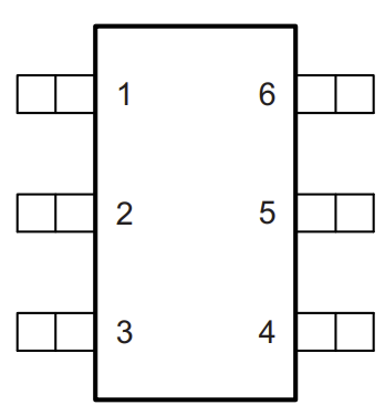
Pin Configuration and Descriptions
The TPS22918 is available in a 6-pin package. Below is the pinout and description:
SOT-23 Package Pinout
| Pin Number | Pin Name | Description |
|---|---|---|
| 1 | VIN | Input voltage supply |
| 2 | GND | Ground connection |
| 3 | ON | Enable pin (active high) |
| 4 | NC | No connection |
| 5 | VOUT | Output voltage to the load |
| 6 | NC | No connection |
WCSP Package Pinout
| Pin Number | Pin Name | Description |
|---|---|---|
| A1 | VIN | Input voltage supply |
| A2 | ON | Enable pin (active high) |
| B1 | GND | Ground connection |
| B2 | VOUT | Output voltage to the load |
Usage Instructions
How to Use the TPS22918 in a Circuit
- Power Supply: Connect the input voltage (VIN) to the power source. Ensure the voltage is within the range of 1 V to 5.5 V.
- Enable Pin: Use the ON pin to control the switch. Drive the ON pin high (above 1 V) to enable the switch and allow power to flow to the load. Drive it low (below 0.4 V) to disable the switch.
- Output Connection: Connect the load to the VOUT pin. Ensure the load does not exceed the maximum continuous current of 2 A.
- Ground: Connect the GND pin to the system ground.
Important Considerations and Best Practices
- Input Capacitor: Place a 1 µF ceramic capacitor close to the VIN pin to stabilize the input voltage.
- Output Capacitor: Use a 0.1 µF to 10 µF capacitor at the VOUT pin to improve transient response and stability.
- Thermal Management: Ensure adequate thermal dissipation, especially in high-current applications.
- Enable Pin Control: Avoid floating the ON pin. Use a pull-down resistor if the pin is not actively driven.
- Protection Features: The TPS22918 includes over-current and thermal shutdown protection. Ensure the load does not exceed the rated current to avoid triggering these protections unnecessarily.
Example: Using TPS22918 with Arduino UNO
The TPS22918 can be controlled using a GPIO pin from an Arduino UNO. Below is an example circuit and code:
Circuit Connections
- Connect VIN to a 5 V power source.
- Connect VOUT to the load (e.g., an LED with a current-limiting resistor).
- Connect the ON pin to a digital GPIO pin on the Arduino (e.g., pin 7).
- Connect GND to the Arduino's ground.
Arduino Code
// Define the GPIO pin connected to the ON pin of TPS22918
const int loadSwitchPin = 7;

void setup() {
  // Set the load switch pin as an output
  pinMode(loadSwitchPin, OUTPUT);

  // Turn off the load switch initially
  digitalWrite(loadSwitchPin, LOW);
}

void loop() {
  // Turn on the load switch
  digitalWrite(loadSwitchPin, HIGH);
  delay(5000); // Keep the load on for 5 seconds

  // Turn off the load switch
  digitalWrite(loadSwitchPin, LOW);
  delay(5000); // Keep the load off for 5 seconds
}
Troubleshooting and FAQs
Common Issues and Solutions
The load does not power on:
- Verify that the ON pin is driven high (above 1 V).
- Check the input voltage (VIN) to ensure it is within the specified range.
- Ensure the load does not exceed the maximum current rating of 2 A.
The device shuts down unexpectedly:
- Check if the thermal shutdown or over-current protection is triggered. Reduce the load current or improve thermal dissipation.
- Verify that the input and output capacitors are properly connected.
High quiescent current:
- Ensure the ON pin is not left floating. Use a pull-down resistor if necessary.
Slow switching times:
- Verify the input capacitor value. A 1 µF capacitor is recommended for optimal performance.
FAQs
Q: Can the TPS22918 handle reverse current?
A: No, the TPS22918 does not support reverse current blocking. Ensure the output voltage does not exceed the input voltage.
Q: What happens if the load exceeds 2 A?
A: The over-current protection feature will activate, shutting down the device to protect it from damage.
Q: Can I use the TPS22918 with a 3.3 V microcontroller?
A: Yes, the ON pin is compatible with logic levels as low as 1 V, making it suitable for 3.3 V systems.
Q: Is the TPS22918 suitable for high-frequency switching?
A: The TPS22918 is optimized for power management and not designed for high-frequency switching applications.