Cirkit Designer
Your all-in-one circuit design IDE
Home /
Component Documentation
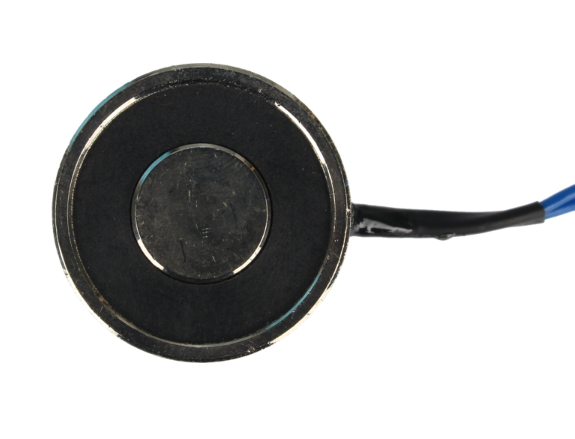
How to Use Electromagnet: Examples, Pinouts, and Specs
Introduction
An electromagnet is a type of magnet in which the magnetic field is produced by an electric current. It typically consists of a coil of wire wound around a core of iron or another ferromagnetic material. Electromagnets are widely used in various applications due to their ability to be turned on and off with the flow of electric current.
Explore Projects Built with Electromagnet
Arduino Nano 33 BLE Magnetic Levitation System with Hall Sensor Feedback and Status LED Indicator

This circuit is designed for a magnetic levitation system that uses a Hall sensor to detect magnetic field strength and a TIP120 transistor to control the current through a levitating coil. An Arduino Nano 33 BLE microcontroller reads the sensor and adjusts the coil current via PWM to maintain levitation, while an LED indicates the system's status. The circuit includes power management with 5V DC sources and protective components like diodes and resistors for current control and indication.
Copper Coil Multimeter Measurement Circuit
This circuit consists of two copper coils connected in series, with one of the coils having additional taps for positive and negative connections. A multimeter is connected across one of the coils to measure voltage across it. The purpose of this circuit could be to demonstrate electromagnetic induction or to measure the induced voltage in one of the coils when a current flows through the other.
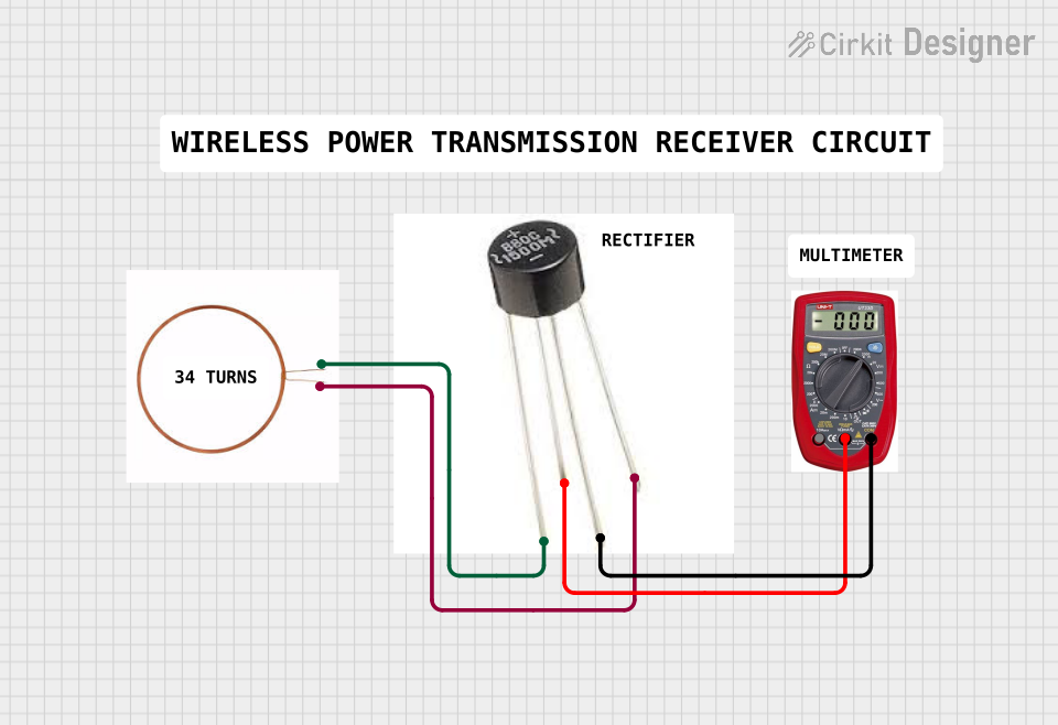
Arduino-Based Wireless Power Transmission System with Copper Coils

This circuit consists of multiple copper coils connected to transmitters and a receiver, likely forming a wireless power transfer or communication system. The transmitters are connected to individual coils, and the receiver is connected to another coil, facilitating the transmission and reception of signals or power wirelessly.
Arduino UNO-Based Battery-Powered Robotic System with Ultrasonic Sensors and Magnetometer
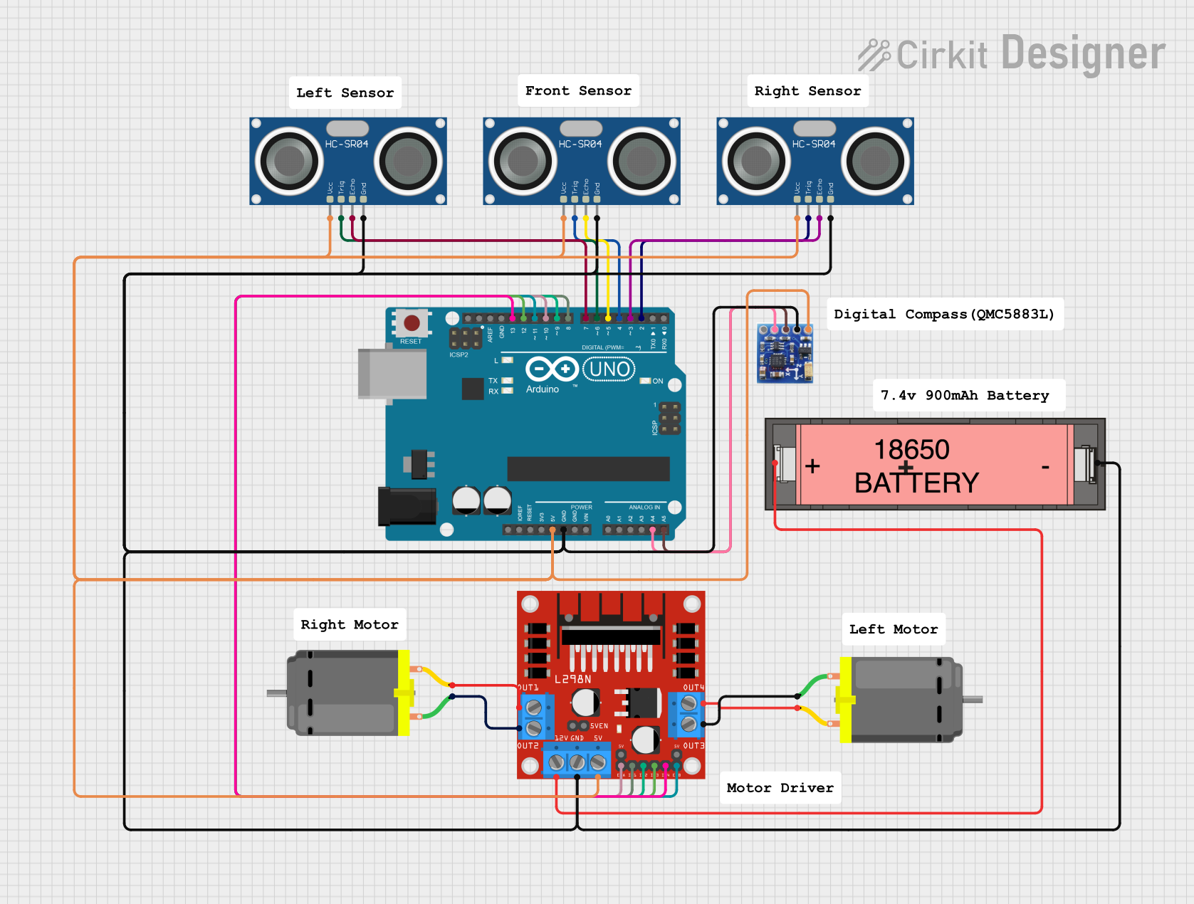
This circuit is a sensor-based robotic system controlled by an Arduino UNO. It includes three HC-SR04 ultrasonic sensors for distance measurement, a QMC5883L magnetometer for orientation detection, and an L298N motor driver to control two DC motors, all powered by a Li-ion 18650 battery.
Explore Projects Built with Electromagnet
Arduino Nano 33 BLE Magnetic Levitation System with Hall Sensor Feedback and Status LED Indicator
This circuit is designed for a magnetic levitation system that uses a Hall sensor to detect magnetic field strength and a TIP120 transistor to control the current through a levitating coil. An Arduino Nano 33 BLE microcontroller reads the sensor and adjusts the coil current via PWM to maintain levitation, while an LED indicates the system's status. The circuit includes power management with 5V DC sources and protective components like diodes and resistors for current control and indication.
Copper Coil Multimeter Measurement Circuit
This circuit consists of two copper coils connected in series, with one of the coils having additional taps for positive and negative connections. A multimeter is connected across one of the coils to measure voltage across it. The purpose of this circuit could be to demonstrate electromagnetic induction or to measure the induced voltage in one of the coils when a current flows through the other.
Arduino-Based Wireless Power Transmission System with Copper Coils
This circuit consists of multiple copper coils connected to transmitters and a receiver, likely forming a wireless power transfer or communication system. The transmitters are connected to individual coils, and the receiver is connected to another coil, facilitating the transmission and reception of signals or power wirelessly.
Arduino UNO-Based Battery-Powered Robotic System with Ultrasonic Sensors and Magnetometer
This circuit is a sensor-based robotic system controlled by an Arduino UNO. It includes three HC-SR04 ultrasonic sensors for distance measurement, a QMC5883L magnetometer for orientation detection, and an L298N motor driver to control two DC motors, all powered by a Li-ion 18650 battery.
Common Applications and Use Cases
- Relays and Switches: Used in electrical relays and switches to control circuits.
- Motors and Generators: Integral components in electric motors and generators.
- Magnetic Lifting Devices: Used in cranes and other lifting devices to move heavy ferromagnetic materials.
- Magnetic Locks: Employed in security systems for doors and safes.
- Medical Devices: Utilized in MRI machines and other medical equipment.
Technical Specifications
Key Technical Details
| Parameter | Value |
|---|---|
| Operating Voltage | 5V to 12V DC |
| Current Rating | 500mA to 2A |
| Power Rating | 2.5W to 24W |
| Coil Resistance | 2.5Ω to 24Ω |
| Core Material | Iron or other ferromagnetic material |
| Magnetic Field Strength | Up to 1 Tesla |
Pin Configuration and Descriptions
| Pin Number | Pin Name | Description |
|---|---|---|
| 1 | VCC | Positive supply voltage (5V to 12V) |
| 2 | GND | Ground |
Usage Instructions
How to Use the Component in a Circuit
- Power Supply: Connect the VCC pin to a suitable power supply (5V to 12V DC) and the GND pin to the ground.
- Control: Use a switch or a transistor to control the flow of current through the electromagnet.
- Protection: Include a flyback diode across the electromagnet to protect against voltage spikes when the current is switched off.
Important Considerations and Best Practices
- Current Limiting: Ensure that the current through the electromagnet does not exceed its rated value to prevent overheating.
- Heat Dissipation: Provide adequate ventilation or heat sinking to dissipate heat generated during operation.
- Power Supply: Use a stable and regulated power supply to ensure consistent performance.
- Switching: Use a suitable transistor or relay to switch the electromagnet on and off, especially when interfacing with microcontrollers like Arduino.
Example Circuit with Arduino UNO
/*
 * Example code to control an electromagnet using Arduino UNO
 * The electromagnet is connected to pin 9 through a transistor
 */

const int electromagnetPin = 9; // Pin connected to the transistor base

void setup() {
  pinMode(electromagnetPin, OUTPUT); // Set pin as output
}

void loop() {
  digitalWrite(electromagnetPin, HIGH); // Turn on the electromagnet
  delay(1000); // Keep it on for 1 second
  digitalWrite(electromagnetPin, LOW); // Turn off the electromagnet
  delay(1000); // Keep it off for 1 second
}
Troubleshooting and FAQs
Common Issues Users Might Face
Electromagnet Not Turning On:
- Solution: Check the power supply connections and ensure the voltage is within the specified range. Verify that the control signal from the microcontroller or switch is functioning correctly.
Overheating:
- Solution: Ensure that the current through the electromagnet does not exceed its rated value. Provide adequate ventilation or heat sinking.
Weak Magnetic Field:
- Solution: Verify that the power supply voltage and current are sufficient. Check for any loose connections or high resistance in the circuit.
Solutions and Tips for Troubleshooting
- Check Connections: Ensure all connections are secure and correct.
- Measure Voltage and Current: Use a multimeter to measure the voltage and current to ensure they are within the specified range.
- Inspect Components: Check for any damaged components, such as burnt-out transistors or resistors.
- Use Flyback Diode: Always include a flyback diode across the electromagnet to protect against voltage spikes.
By following this documentation, users can effectively utilize an electromagnet in their electronic projects, ensuring reliable and efficient operation.